Search This Blog

Thursday, December 23, 2021

Flashlight 3xAAA replacement

​I got a flashlight as the first ever kind gesture from my apartment management for the most recent schedule 24+hours maintenance power shutoff. It has a very nice reflector for a square LED and a smaller chip inside that controls the 3 operating modes. 

Off course I had to open it up right away.  It uses 3AAA on the usual battery holders for cheap flashlights.  I smell trouble or an opportunity for some corrective active.  I am not fond of using odd numbers of AAA batteries as I have been using rechargeable since NiCd days.  I don't know if they use a constant current driver, so could be trouble for 3 fully charged NiMH (1.4V x 3 = 4.2V) with low internal resistance.

I used the parts from a 5V booster board I bought from the usual places, but modified the feedback divider for 3V which is just bright enough to drive LED, but low enough to not go into thermal run away.

U1 has the same pin out as the unknown part used on the board.

As my replacement board has 3 contacts - 3V and 2 GND, I had to move the battery off centered to avoid shorting the 3V output to the front of the PCB.  

I used easily soldered and bent metal strips  to form a battery guide and the hinged -ve terminal.  They are used to crimp the end of plastic mesh for store bought onions and garlic.  

My battery terminal help to make better connection between the offset battery and the spring loaded terminal the of the flashlight cap to the right side of the picture below.


It also acts as a pull tab for the PCB assembly when it is time for replacing battery.


Attack of the blinking dimming flashlight

I would never have thought that the blinking dimming light movie tropes is being kept alive by poorly made flashlight clicky switches.

I managed to extract the mechanism that was pressed fitted into the end cap of the flashlight.  They use some iron strips as part of the contact.  There are 2 such contacts in series and they gets even worse as I use the switch for the boost supply with about 3X currents.


I cut2 pieces of gold plated (15um) pin from a 2mm connector.


I soldered them onto the contacts.  The contacts needed to be bent flat as the pins adds extra thickness.


There is a metal piece that looks like a top in the previous picture.  I had to bent the circular part down to make more clearance for the pins. I reassembled the switch and soldered a short piece of bare stranded wires.  This wire helps to make better contact to the side wall of the end cap.


Unfortunately the plastic they used is too soft and I do not have the right jig to press it back in place.  If there were a time I wish I had a 3D printer, this would be it.

Anyways this fix got rid of the flimsy flickers and the light a lot brighter.


DIY Amplifier collection

Here are some of my DIY amplifier collections:

I built one of these back in my school days out of a pair of TI/National Semiconductor's Class A-B LM1875 20-W Audio Power Amplifier. Build straight out of their application circuits. I mounted in 2 of these amplifier into a 60W heatsink.

I recapped, cleaned up the layout and mounted it with a Transformer (33V CT 1A), rectifiers (200V/3A) and filter caps (1000uF x 4) onto a piece of board from a clementine box.  It served as my TV/Computer amplifier for about a year.


It was from the days of good old analog design with honest specs.  Note their 20W is at the lowest THD.  


They have excellent PSSR (Power Supply Rejection Ratio) around 95dB at 120Hz.  I can simply run it off a full wave rectifier from a transformer.  They aren't too efficient, so my choice of 60W heatsink was appropriate for continuous operation of 2 amplifier at full power.


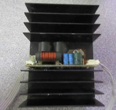
I later built a few of the 60W module out of a pair of TI/National Semiconductor LM3886 68W Class-AB amplifier.  (I didn't have a LC meter, so the inductance value on that coil as way too low.)


Sadly at that point I gave into craze and bought myself a  surround sound receiver. I sworn to rip out and replace the "discrete" amplifier at the expiration date of the warranty, but didn't follow through.

They are probably one of the better if not the best chip amplifier that a lot of the DIY amplifiers designs are based on.

However you would want to use 4ohms speakers to take advantage for the full rated power at low distortion.  


Recently, I started playing around with those Class D modules from China to connect to my computer surround sound analog output.  I tried the $0.30 PAM8403 modules but there was a lot of noise for my rear speaker probably due to the parasitic of the longer cables.  I went for the PAM8610 "10W" modules.  The first one was bad as it took too much design freedom.  

I then read the reviews and moved on to the "better" version of the module that did follow the reference design. I wish they break out the volume control and the balanced input.

I mounted 3 of those modules onto a extruded heatsink from an old monitor.  The heatsink is probably good for up to 10W. I covered area on the bare aluminium heatsink  with "Kapton" tape where I have wire connections.  I used pieces of thermal conductive tape on the thermal vias under the chip to carry heat to the heat sink.  The heatsink tape I used was electrically conductive, so the heatsink and the metal case was grounded because of that.

I ran a power bus with a 1000uF electrolytic cap and a few 1uF ceramic caps near each of the power input of the amplifier blocks.  There is a ferrite bead for each amplifiers to block the high frequency noise injecting back to the VCC bus rail. I didn't have the same layout for the amplifier at the bottom and it was a bit noisier.  The layout in the picture below fixed that.


The heatsink was mounted at the opposite to the messy wiring which helps a bit to balance the drag from the wires.


Here is why i used air quotes on "10W" as I am using a 9V supply, so I would be happy to get 5W out of mine.

The PSRR isn't as good as my other amplifiers.  I actually can hear 60Hz hums using AC transform + rectifier.  I ended up using a good quality 9V 40W brick, so 5W per channel was the best I can hope for anyway.
Either I have insanely good ears for the hiss or the -90dB isn't quite feasible without a lot of work.  I can't hear any noise from my 20W Class A-B.


It is not a perfect set up, but it is good enough for me for now.


Friday, December 10, 2021

NiMH Battery backup

Battery compartment of my digital clock project (Caller ID case)

The power in my apartment used to be very reliable, but things have deteriorated in the last 10 years or so.  I have experienced serval power outage and some up to 6-7 days.

The Supercap I have is only good for a few minutes as the STM8 clock uses around 2mA to keep its firmware RTC working at the minimal state.  It requires a minimum of 3V, so Li coin cells are out. I don't quite trust Li-ion batteries enough to be trickle charge 24/7. 

I use some old NiMH batteries.  They lost most of their capacity, but they are still good for a few mA load. They are sitting in a compartment at the bottom of the clock, so gravity would protect the electronics from any leaks.

Here is a battery backup for the digital clock. +5V is the power source (e.g. USB) that can go away and +UB is the backup rail.


So, NiCd's are super easy to charge. You just throw current into them at about 0.1C, and once they're full, they turn the rest into heat. Harmlessly, and forever. You can just slowly overcharge NiCd and it's fine with that. Lots of old two-way battery cradles did just that, and it's why the radios were always warm when you picked them up. 
Do that to NiMH, and they "vent". NiMH needs charge termination, or needs to be floated at a lower voltage so it never gets quite "full". Right around 1.35 volts per cell seems happy.

You'll notice it a bit funny as the LTC4054ES5 is a Li-ion charger chip and I am using it for NiMH. It turns out that 3 NiMH has just around the same charge voltage as Li-ion battery.  (The minimum charging current for this chip is 50mA.)

The -ES5 part has a recharge threshold of -150mV, so it would starts charging the batteries when they drop to 1.35V each.  It charges the cells at 50mA to about 1.4V and stop charging when the charge current is below 5mA.  

I use a P-MOSFET (Q1) as a switch for the back up rail to reduce the voltage drop vs a Schottky diode.

This has been working for close to half a year now without any leaks.  It also survived a 24+ hour of back out with plenty of  juice left.

Friday, November 26, 2021

Boring PC case mod with recycled materials

I bought a new CPU and a motherboard from a Black Friday sales.  It is like a reverse hermit crabs upgrade with each of  my PC downsize to an older case.  The old $20 thrift store P4 Dell lost in the musical chair to my older FM1 PC.  It has PCI, PCIe, Parallel, Serial port (header) and no Pesky Security Processor (PSP).

You may think that stuffing a mini-ATX board into a mini-ATX case is straight forward, but this isn't the case here.

One of the most annoying thing about the Dell Dimension 3000 is the missing Reset button.  The Dell case has a removable cover and uses push rods for the buttons and light pipes for the LED.  Their push rods are mounted from behind the front cover.  Instead of a long dangling wire for a quick and dirty mod,  I have decided to follow the flow as it is a bit easier for maintenance.

It ain't pretty, but it does the job

I used a ball point pen for the push rod.  It was one of those freebies I got from either a trade show or a vendor.  It has just the right length and right push button.  I used some hot glue to attach it to the middle piece behind the front case panel.  I extended the other end with an empty pen cartridge cut to the right length for the push button.  I used the mounted ballpoint pen part as a guide for my drill bit for the metal panel and the front cover.


The diameter of this cartridge is a loose fit over the narrow part of the push button.

Back side of the panel

I use a (grey) PCV insulation from a power cord on the transparent tubing to stop the push rod from falling out the front. 


I used a nibbler to cut out a slot for the panel mount Reset switch from an old PC.  I could have solder a push button onto a small PCB and mount it to the case with a spacer.

I was going to use the existing hole below it, but it was a bit too closed to the On/Off button mechanism.  It was probably for an optional LED illuminating the On/Off switch.

The new Reset button in the full depressed state.

Dell uses a swing out removable vertically mounting bracket for the 3.5" HDD.  I made a mounting bracket for 2.5" SSD with 100% recycled DIMM PCB.  I used a nibbling tool to cut the slot that was needed to clear the bracket.  The bracket is mounted to the HDD screw holes.


I have a left over AMD Ryzen 7 1700 Wraith Spire Coolers.  Too bad they change the mounting brackets in the AM4 socket the the old FM1 days, but doesn't stopped me from replacing the fan on the old stock cooler.   The larger fan is quiet with a lot more air flow.

I was going to make a two piece mounting bracket as an adapter for the larger fan, but it was too much work.  It turns out that all I needed was 4 short strips of old FR4 PCB.  They are mounted diagonally with 4 screw to the original heatsink mounting holes and another 4 to the larger fan.  I offset the fan so that it would clear the heatsink latch mechanism.

FR4 strips mounted to the heatsink

The fan is then mounted with 4 screws onto the FR4 strips.


This is what the internals looks like when the AMD logo is lit up.


Thursday, May 13, 2021

STM8 Gyrostock


STM8S003 + MPU6050 module

I was inspired by Cemu Gyro Joystick project which is a way to add motion data to a regular game controller. My hardware is based on cheap MPU6050 modules that was used by Gyro_Joystick from the project. 

I have ordered some USB hub chips from some dodgy supplier, but they turned out to be fake - blanks. So much for trying to squeeze it inside the controller and share the same USB connection.

Possible mounting location

It uses a firmware based USB library on a STM8S003 and communicates with the MPU6050 via I2C bus. The I2C peripheral comes with several errata with work arounds.


All would be fine except that both the firmware only USB and now I2C drivers relies on interrupts and tight timing.  I have implemented an interrupt driver based on ST's App. Note: AN3281 - STM8 8-bit MCUs I2C optimized examples It improved the reliability a bit over some other I2C drivers I was trying but it still hangs under load.

I looked at the USB traces and found that the I2C started in the middle of USB communication and cause it to hang eventually. 

Time delay

By adding a bit of time delay before the I2C transfer, I was able to fix the issue.  Now each of them gets their undivided attention from the CPU.

USB packet followed by I2C traffic

USB specs limits a Low Speed device to 8 bytes interrupt packets which is what's used for HID reports.  

6 axis at 16-bit each is 6 x 2 bytes = 12 bytes!

I have tried several things and failed.  The only way I could send out 6 axis full 16-bit data is to logically group the Accelerometers and Gyroscopes under separate Report ID and alternating between the two reports.

HID Report Descriptors
Thankfully that the host side picks up the 2 reports and treats them as one set of data (at 1/2 the data rate).Windows recognize this as a 6-axis game controller - (X/Y axis + 4 sliders).

Windows Game controller setting

The next part is to figure how to compile the Cemu Gyro Joystick project as they didn't have a pre-compiled version and I haven't got a clue on NodeJS.

Mechanicals

I have added Sketchup model for people who have fancy 3D printer(s).  I on the other hand tried to make a mount with simple hand tools. 
Sketchup 3D model

It is a home made captured M3 nut on a piece of PCB.  I drill an undersized hole and hand filed a hexagon hole. With the help of a pier and some applied force, I pressed it into the hole.  The nut bites into the slightly under sized hole and held in place. 

I cut a small piece of plexiglass with a saw blade attached to a Dremel tool.  I used a hand drill to drilled 2 holes - one  for the screw and a larger one the nut.

PCB assembly, plexiglass spacer, captured nut + M3 screw

Note the edge of the plexiglass is flush with the module and this helps to prevent the PCB assembly from spinning.


The plexiglass is then superglued to the captured nut PCB to form a mount.  I screwed in the PCB assembly to show how things fitted together. Notice the white stress points on the FR4 at the corner of the nut.  That's what holding the nut in place (along with the superglue).  FR4 can handle stress a lot better than plexiglass.  The thickness is just right for the M3 screw and clears the PCB assembly.  :)


The base can then be superglued to a controller.  My has a label area.

Homemade mount that can be glued to game controller

Here is what it looks like with everything in place.  The PCB components are protected by the back side.  The PCB assembly can be easily removed for easy access.


Github files

Conclusion

It would seem that this project is a partial failure as I have failed the objective.  It is not compatible with Cemu Gyro Joystick as it is limited by USB Low Speed to 8-byte interrupt packets size.  Node.JS is a mess to work with especially with the whole ball of wax of imported dependency.  Chances of fixing it is NIL.I have toyed with the idea of writing a program from scratch, but lost interest.

I have integrated an Interrupt driven I2C host with VUSB.  I have tested the idea of using multiple ReportID as a way to bypass the 8-byte packet limit.


Monday, March 8, 2021

STM8 Timer V2

 Go to Timer V1

Timer V2

There were a few changes to the V1 design.

  • Supercap backup power

  • Connectors for LED/sensor and Servo connector

  • Switcher module

  • LCD and buttons I/O changes. LCD backlight on/off control by ambient light

  • I2C connector

  • expansion connector for nRF24 (no firmware support)

Supercap backup power

Supercap backup

The backup circuit is similar to the one I have been using in my digital clocks.  I added the option of using a constant current source for charging the low ESR supercap. The resistor is simpler and have one less diode drop.

Servo connector

It turns out that the water pump I originally used wasn't reliable, so I have been using a servo driven valve.  I had to rerouted the control line for power supply the servo.  

Switcher module

5V supply

A DC-DC converter module is used for converting the 12V to 5V for the timer and servo.  I used a 10K resistor to set the output of the KIS-3R33 module to 5V.  Other modules can be used.

I am using power supply grade Tantalum capacitors as they take up less heights and offers a longer lifetime than electrolytic capacitors. The DC-DC module operates at 340kHz which helps to reduce the capacitance.

LCD and buttons I/O changes

I have decided to use time delay instead of polling for Busy Flag for the LCD.  This frees up 1 GPIO pin and simplifies the sharing of the LCD I/O signals for multiple functions.

Buttons

In the V1 design, an ADC channel is used for sensing the buttons.  The LCD data lines now are used for polling the buttons.

nRF24 module

Also new in this version is a connector for a nRF24 module.  The module uses SPI which shares the same data lines with the LCD. 

Timer with the nRF24 module

A bottom entry connector is used for flush mounting the nRF24 module.


github: https://github.com/FPGA-Computer/Timer