LED test - powered from a bench supply
The light strip consists of 3 PCB and a few 3D printed parts.
I used pieces of 12V LED strips soldered onto a PCB. The strips are wired in series so that they would operate at 24V.
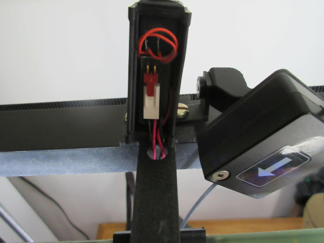
The 2 light strip PCB are assembled into the 2 PCB holder pieces with channels in the middle for wiring. The are joint to a T shaped piece in the middle. The 2 side PCB are wired in parallel. A 100K resistor (R9) has been added in parallel to the LED strips as the LED are sensitive enough to turns on through the 2200K feedback resistor.
The LED lightbar assembly is attached to the base with a M3 screw and a captured nut. This forms an adjustable arm.
Here is the LTSpice simulation I used for the optional LED sensor. The 2 comparators operates as a windows detector. The lower threshold determines when the light turns on while the upper threshold is when all the lights are off.
As the LDR (R4) has a wide dynamic range, I have decided to inject the hysteresis at the reference by a positive feedback resistor R6. It is driven from the MOSFET output which added a 180 degrees phase shift. A capacitor C1 is added to suppress the oscillation during the on/off transitions.
V2 is used for simulating the LDR sensor by sweeping the range of voltages.
 |
| Blue trace: Comparator input Green Trace: LED strip voltage |
The following are the schematic and layout of the sensor.
The circuit board is fasten to the printed housing with double sided silicon adhesive tape. The power switch is snapped into the opening in the front. The circuit is powered from the internal 24V power supply located at the base of the printer just like the official lightbar. There is a connector for the 24V.
I used a heatshrink tubing to block off light entering to the sensor from the sides.
I routed the wires next to the one used by filament sensor into the extruded aluminum frame on the left side.
This is a special one off design as the resistor values are empirically determined by the ambient light at my specific location and the electrical characteristics of the LDR I am using.
I could have used trimpots for the thresholds. The light sensor could have been implemented using a microcontroller like my Timer project.
Files are released under: https://github.com/FPGA-Computer/3D-Printer-projects/tree/master/Creality%20Ender%20V3%20KE/Lightbar


