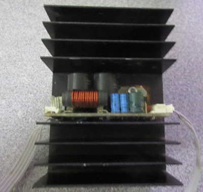
Here are some of my DIY amplifier collections:
I built one of these back in my school days out of a pair of TI/National Semiconductor's Class A-B LM1875 20-W Audio Power Amplifier. Build straight out of their application circuits. I mounted in 2 of these amplifier into a 60W heatsink.
I recapped, cleaned up the layout and mounted it with a Transformer (33V CT 1A), rectifiers (200V/3A) and filter caps (1000uF x 4) onto a piece of board from a clementine box. It served as my TV/Computer amplifier for about a year.
It was from the days of good old analog design with honest specs. Note their 20W is at the lowest THD.
They have excellent PSSR (Power Supply Rejection Ratio) around 95dB at 120Hz. I can simply run it off a full wave rectifier from a transformer. They aren't too efficient, so my choice of 60W heatsink was appropriate for continuous operation of 2 amplifier at full power.
I later built a few of the 60W module out of a pair of TI/National Semiconductor LM3886 68W Class-AB amplifier. (I didn't have a LC meter, so the inductance value on that coil as way too low.)
Sadly at that point I gave into craze and bought myself a surround sound receiver. I sworn to rip out and replace the "discrete" amplifier at the expiration date of the warranty, but didn't follow through.
They are probably one of the better if not the best chip amplifier that a lot of the DIY amplifiers designs are based on.
However you would want to use 4ohms speakers to take advantage for the full rated power at low distortion.
Recently, I started playing around with those Class D modules from China to connect to my computer surround sound analog output. I tried the $0.30 PAM8403 modules but there was a lot of noise for my rear speaker probably due to the parasitic of the longer cables. I went for the PAM8610 "10W" modules. The first one was bad as it took too much design freedom.
I then read the reviews and moved on to the "better" version of the module that did follow the reference design. I wish they break out the volume control and the balanced input.
I mounted 3 of those modules onto a extruded heatsink from an old monitor. The heatsink is probably good for up to 10W. I covered area on the bare aluminium heatsink with "Kapton" tape where I have wire connections. I used pieces of thermal conductive tape on the thermal vias under the chip to carry heat to the heat sink. The heatsink tape I used was electrically conductive, so the heatsink and the metal case was grounded because of that.
I ran a power bus with a 1000uF electrolytic cap and a few 1uF ceramic caps near each of the power input of the amplifier blocks. There is a ferrite bead for each amplifiers to block the high frequency noise injecting back to the VCC bus rail. I didn't have the same layout for the amplifier at the bottom and it was a bit noisier. The layout in the picture below fixed that.
The heatsink was mounted at the opposite to the messy wiring which helps a bit to balance the drag from the wires.
Here is why i used air quotes on "10W" as I am using a 9V supply, so I would be happy to get 5W out of mine.
The PSRR isn't as good as my other amplifiers. I actually can hear 60Hz hums using AC transform + rectifier. I ended up using a good quality 9V 40W brick, so 5W per channel was the best I can hope for anyway.
Either I have insanely good ears for the hiss or the -90dB isn't quite feasible without a lot of work. I can't hear any noise from my 20W Class A-B.
It is not a perfect set up, but it is good enough for me for now.


