I haven't fixing my old servo as I can get cheap micro servos from the usual place for a few dollars. Those servos are very fast and quite strong for their size.
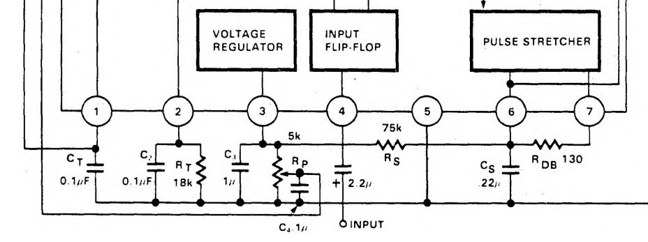 I knew something was wrong as the motor spins for a few seconds when I applied power. Cs for the Pulse Stretching is labelled as .22uF, but the '.' was missing on one of the datasheet. I didn't know at the time that the value I put in was 2 orders of magnitude higher!


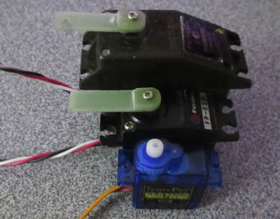
Old servo vs newer Tower Pro S90
I took the 10 minutes to make a replacement Servo arm out of FR4 PCB.
This is one reason why I don't trust scanned datasheet and inconsistent component values labelling. On the old datasheet scan I had, the critical '.' was missing. Had they use a '0' in front consistently, that wouldn't have been a problem.

I figured that Rs * Cs time constants should be on the order of 20ms (1/50Hz). 50Hz being the frequency of the control PWM. ~ 0.266uF close enough to the 0.22uF value.
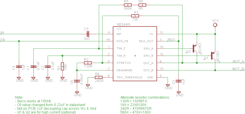
I still have some doubt to the actual value as they used 0.1uF else where on the datasheet with a leading '0', but without one on the .22Uf. The first value I tried was 0.56uF as it fitted the footprint I had for Cs. It was a luck of the draw as it work better than the 0.22uF. There was some rattling with the 0.22uF, but 0.56uF was fine. It might be something related to dead band setting as that servo have a lot of backlash.
I just noticed that C4 filter cap for the feedback signal also has the extra '.' in front! I used 1uF as the old datasheet scan didn't have it. For my slow servo, it makes very little difference.

I had to make up the proper values of the resistors as I don't have them in my parts box.

I have enough space, so I also put in the two optional PNP transistors on the PCB for high currents motors.

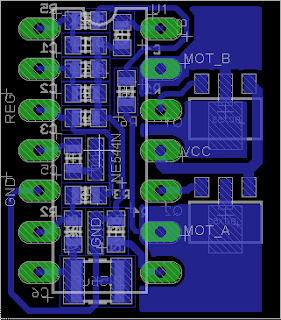
PCB back side

PCB Top side
I drilled extra holes for a 1uF decoupling cap across pin 5 & 11 of the NE544 as I missed that on my PCB.

Old picture with a 0.22uF decoupling cap on back side.
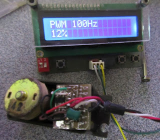
I used my Component Tester to generate a PWM as the test signal. The 100Hz was as low as the tester would go. The nominal PWM frequency for servos are around 50Hz. The NE544 circuit and 70% of my servos works at the faster rate of 100Hz.
This PCB could be useful if I ever need to make a servo out of some random geared motor assembly.