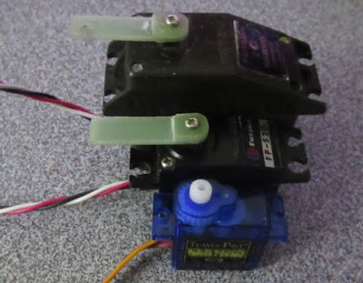
I haven't fixing my old servo as I can get cheap micro servos from the usual place for a few dollars. Those servos are very fast and quite strong for their size.
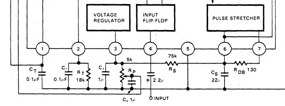 I knew something was wrong as the motor spins for a few seconds when I applied power. Cs for the Pulse Stretching is labelled as .22uF, but the '.' was missing on one of the datasheet. I didn't know at the time that the value I put in was 2 orders of magnitude higher!


Old servo vs newer Tower Pro S90
I took the 10 minutes to make a replacement Servo arm out of FR4 PCB.
This is one reason why I don't trust scanned datasheet and inconsistent component values labelling. On the old datasheet scan I had, the critical '.' was missing. Had they use a '0' in front consistently, that wouldn't have been a problem.

I figured that Rs * Cs time constants should be on the order of 20ms (1/50Hz). 50Hz being the frequency of the control PWM. ~ 0.266uF close enough to the 0.22uF value.
I still have some doubt to the actual value as they used 0.1uF else where on the datasheet with a leading '0', but without one on the .22Uf. The first value I tried was 0.56uF as it fitted the footprint I had for Cs. It was a luck of the draw as it work better than the 0.22uF. There was some rattling with the 0.22uF, but 0.56uF was fine. It might be something related to dead band setting as that servo have a lot of backlash.
I just noticed that C4 filter cap for the feedback signal also has the extra '.' in front! I used 1uF as the old datasheet scan didn't have it. For my slow servo, it makes very little difference.

I had to make up the proper values of the resistors as I don't have them in my parts box.

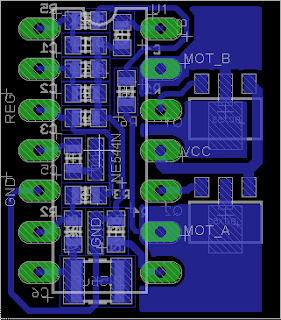
I have enough space, so I also put in the two optional PNP transistors on the PCB for high currents motors.

PCB back side

PCB Top side
I drilled extra holes for a 1uF decoupling cap across pin 5 & 11 of the NE544 as I missed that on my PCB.

Old picture with a 0.22uF decoupling cap on back side.
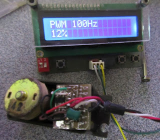
I used my Component Tester to generate a PWM as the test signal. The 100Hz was as low as the tester would go. The nominal PWM frequency for servos are around 50Hz. The NE544 circuit and 70% of my servos works at the faster rate of 100Hz.
This PCB could be useful if I ever need to make a servo out of some random geared motor assembly.
I replaced the PCB in the smaller servo. The original PCB used a SIP part. The SMT version of the NE544 would have help, but I could only get hold of the DIP version. Obviously that won't fit without some effort.

Size comparison of Servo PCB vs DIP
The following shows the lead frame for a DIP package before the silicon die is wire bonded and molded. The rectangle in the middle is for the silicon die.
I trimmed the ends off the package (see LM393N above) and chamfered the two ends of the DIP package after it was soldered and tested.

Lead frame of a16-pin DIP for the base for the silicon chip and pins
I changed back the dead band capacitor to 0.22uF as this servo is much quicker and have less backlash. They use metal gears with very fine pitch and a ball bearing.
The servo would only work at 50Hz and has a bit more rattling. I guess I should play around with the R2 130R values at some point.

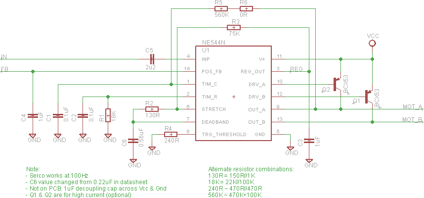
Schematic
I leave out the optional PNP transistors as there isn't space on the PCB. I guess I could make a small daughter card with the transistors if they are needed. I have rearranged the layout so that all the parts fit within the DIP footprint and added 2 jumpers (red).

PCB layout

Replacement PCB

PCB is mounted vertically
I guess someone else could have transplant the PCB from a cheap S90, but that's a bit too boring for me.
No comments:
Post a Comment
Note: Only a member of this blog may post a comment.