Search This Blog

Friday, December 30, 2022

DIY Dell Dimension 3000 heatsink fan

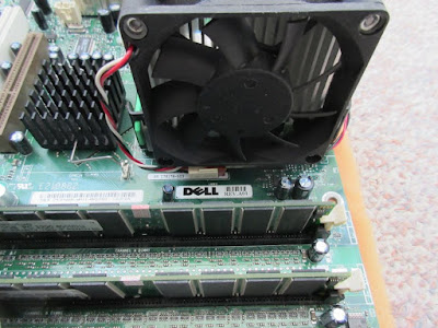
As a result of my previous Boring PC case mod with recycle material, the Dell motherboard was left without a  heatsink fan.

Replacement fan for the heatsink

Dell use a "airflow shroud" to funnel airflow over their CPU heatsink via the case fan.  They do so to cut their BOM cost as they control both their motherboard layout as well as their case design.

Exhaust fan + airflow shroud

Heatsink + retention base

I could probably find a heatsink to replace the whole setup from the usual places from China, but I have already spent too much on an obsoleted platform.

I have decided to mount the fan for a front to back airflow as shown in my first picture to fit a 70mm fan: Cofan F-7015H12B.  Here are its specs:

I cut a couple of blank FR4 PCB and tapped in #4-40 screw threads for mounting the fan.  Originally I tried to superglue the FR4 onto the Lexan retention base, but it didn't hold.  I glued it again, but reinforced with screws.

FR4 mounts for fan

I use a milling bit to the area for the screw.


Here is an other view from the back.  I checked to make sure that the nut isn't interfering with the base screw removal nor the heatsink.


Dell use 2 pieces of extra green clips to "hold" their heatsink by the 2 opposite corners in additional to the middle. I broke one of the pieces earlier.


They use a S shaped bend so that the clips can be inserted/extracted from their slots.  The S bend was where it broke.  I made a crude latch with some transformer I cores. My repaired piece actually holds down the corner of the heatsink. Their S bend adds extra flexibility in the up/down direction which defeats its purpose.  Just waiting for the other piece to break one of these days.


I would try to control the speed of my fan sensing exhaust temperature too.  Here is one of the fan speed controller I built in the past using Microchip TC652.

TC652 fan controller

Advantages:

  • Built-in temperature sensor
  • Uses PWM (~15Hz) to control fan speed
Disadvantage:
  • temperature range by different part numbers of the chip, PWM % not changeable
  • Its PWM interferes with reading fan's speed
I tried my TC652 controller, but ended up with my own discrete design.


R2 = 12K(middle curve) was the right value for my particular fan. 

The next power is the power dissipated by the transistor. Here are the fan currents I measured at different operating voltages with the fan mounted to the heatsink.


The worst case of the transistor power dissipation was around 0.66W, so the part I have should be fine.  

Note: 
The fan sticker as well as data specified 0.4A max.  A blown transistor is the least of my issue if/when the Pentium 4 burnt because of a fan failure/stall.  I would have used a LDO with its thermal protection and larger case for a more robust design.

I attached  fan speed controller to the bottom of the fan with double side silicone tape.  

Discrete fan speed controller

There are black/red wires for power and a ribbon cable for thermistor.  The ribbon cable is routed through the heatsink and retention base. The thermistor is hanging for sensing the exhaust air temperature near the bottom center of the heatsink.

I cut a piece of 90 degrees plastic piece from a food container to block the air from the fan that is above the heatsink.  Fan could have been flush, but height of capacitors was blocking the mounting screws.  A piece of paper is used to prevent air leaking through the otherwise open top of the heatsink.
 

There is an unpopulated 3-pin fan connector near the back of the heatsink.  It is wired on the PCB  in parallel to Dell's non-standard one in the front.


Around the time I started with my fan controller, I ran into the spec of Dell's case fan.

The 3rd wire of Dell's fan isn't the usual /Tach output.  It is open collector/drain and asserts a logic low when the fan is up to speed.  I toke the easy way out by shorting pin 1 and 3 together in my fan cable.  It also mean that the cable does not need to be polarized.

I am hoping to use this motherboard for old parallel port programming dongles and other peripherals that are not supported by their vendors under newer Windows x64 OS.  Sadly that list also include USB, PCI cards..
Tuesday, October 25, 2022

RC servo PCB replacement PCB

I bought some NE544N Servo Amplifier chips from a surplus place in the US a long time ago. That was long before the risk of getting fake chips from China.

I haven't fixing my old servo as I can get cheap micro servos from the usual place for a few dollars.  Those servos are very fast and quite strong for their size.


Old servo vs newer Tower Pro S90

I took the 10 minutes to make a replacement Servo arm out of FR4 PCB.

 This is one reason why I don't trust scanned datasheet and inconsistent component values labelling.  On the old datasheet scan I had, the critical '.' was missing.  Had they use a '0' in front consistently, that wouldn't have been a problem.


I knew something was wrong as the motor spins for a few seconds when I applied power. Cs for the Pulse Stretching is labelled as .22uF, but the '.' was missing on one of the datasheet.  I didn't know at the time that the value I put in was 2 orders of magnitude higher!  

I figured that Rs * Cs time constants should be on the order of 20ms (1/50Hz). 50Hz being the frequency of the control PWM.   ~ 0.266uF close enough to the 0.22uF value.

I still have some doubt to the actual value as they used 0.1uF else where on the datasheet with a leading '0', but without one on the .22Uf.  The first value I tried was 0.56uF as it fitted the footprint I had for Cs.  It was a luck of the draw as it work better than the 0.22uF.  There was some rattling with the 0.22uF, but 0.56uF was fine.  It might be something related to dead band setting as that servo have a lot of backlash.

I just noticed that C4 filter cap for the feedback signal also has the extra '.' in front!  I used 1uF as the old datasheet scan didn't have it.  For my slow servo, it makes very little difference.


I had to make up the proper values of the resistors as I don't have them in my parts box.


I have enough space, so I also put in the two optional PNP transistors on the PCB for high currents motors.

PCB back side

PCB Top side

I drilled extra holes for a 1uF decoupling cap across pin 5 & 11 of the NE544 as I missed that on my PCB.

Old picture with a 0.22uF decoupling cap on back side.

I used my Component Tester to generate a PWM as the test signal.  The 100Hz was as low as the tester would go.  The nominal PWM frequency for servos are around 50Hz.  The NE544 circuit and 70% of my servos works at the faster rate of 100Hz.

This PCB could be useful if I ever need to make a servo out of some random geared motor assembly.

Saturday, January 8, 2022

Intel heatsink mounting brackets on my AM4!

 I bought a Zalman ENPS10X Optima tower heatsink for my old FM1 a long while ago.  It was overkill, but I bought it at a discount. AMD changed the mechanical spec for AM4 socket, so it couldn't be used.

AM4 vs FM1/FM2/AM3


Mounting kit for my old heatsink

Zalman updated the rev. 2 of the heatsink by changing the backplate and the 2 pieces of springs for the AM4 with both sets of mounting holes.  

New heatsink mounting kit

They offer an AM4 upgrade kit for some of their other heatsinks for $11, but not my old model.  That's 1/2 the price of what I paid for and I'll be taking a gamble.  The old springs are too narrow.  I'll have a very hard time trying to drill it without good carbine drill bits and a drill press.  I am using the Intel mounting kit as it leaves just the right amount of space for the extra screws holes.

I placed the heatsink on top of the AMD Wraith Spire.  It turns out that the fan mounting hole lines up with the Intel 775 mounting holes.  I took advantage of that for my alignments.

Zalman heatsink (with Intel mounting kit) on top of Wraith Spire

I use some scrap piece of "stiffener" 0.06" thick plated mild steel from a server card to make my adapter.  I measured off 54mm spacing for the backplate mounting hole.    The hole sizes are 9/64" and all the screws for this project are 6-32.

I use cooking oil as cutting oil for drilling.  Once that's done, I lined it up to my set up and mark off the mounting holes for the springs.  I used the first mounting bracket as a template for the second piece.

My mounting bracket

I got a bit head of myself without thinking about how to equalize the spring tensions of the four corners. The original screws (metric) have short threads. I only have the full thread screws.  I made a wild guess and used some #8 nuts as thick washers that acts as a stop.

Bottom view of the finished bracket
Heatsink mounted using the backplate that came with the motherboard.

The heatsink fits

How well does it works?  I ran P95 for stress testing the set up with a 3.7GHz Overclock and 1.275V undervoltage. The CPU junction temperature is at 75.3C with CPU at around 131W when all fans are running at 100%.  This is actually slightly better than the other heatsink I was using before for the same PC.

Thermal result on my Ryzen 1700

I decided to swap the old heatsink back and use this heatsink with my Ryzen 5800X PC.  I did some minor clean up to replace the screws with pop rivets to make more height clearance for the motherboard components.  This time I super glued the 4 nuts/spacers in place.  I also have to trim off the top left bracket as it was running a bit too close to the VRM capacitors on my new motherboard (not shown).

Heatsink bracket with some minor clean up.

I ran Cinebench as a way to warm up the thermal paste before removing old heatsink.  I used a 2 fans push-pill configuration trying to get the 5800X thermal under control.

The Before picture with the old heatsink (Thermaltake Contac Silent 12)

Here is the same test again with this heatsink also in a push-pull configuration.

The After thermal with this heatsink (Zalman ENPS10X Optima).

The Zalman is about 2.3C cooler and has a slight higher Cinebench R23 score (15225 vs 15133) as it has a slight higher (thermal throttle) frequency limit (4480MHz vs 4475MHz).

Thermaltake probably sourced a commodity heatsink that have the cutouts that supports a rotated orientation not used here. The bottom part (5mm or so) of the fan is not fully covered by the heatsink allowing for  some airflow under the heatsink. For some reasons, they added fins on the baseplate perpendicular (instead of parallel) to the airflow. This messed up the airflow and collects dust.  They also did not include a pair of clips for adding a second fan.

Zalman fan has a higher top RPM and interesting enough they didn't mill the heatpipe flush with the rest of the aluminium baseplate. The top part of their baseplate is smooth.  This would probably help cool the short VRM heatsink down stream.

Thermaltake heatsink side view. Blue arrow show air flow from fan below the heatsink.

The Zalman in my Ryzen 5800X PC.

P95 stress test at Package Power = 100W