Search This Blog

Wednesday, May 8, 2024

CH32V Development with Visual Studio Code/Platform IO: Set up and first impression

Prerequisite:

  • Buy the WCH LinkE Emulation Debugger Module from the usual places from China for less than $5.  You won't even get to the bootstrap loader on the CH32V003 without one as there are no hardware bootstrap pins.  For higher end chips, the bootloader can download from USB using WCHISPTool.


Don't be temped by the cheaper older WCH Link module.  It is powered by CH549 (8051 core with 60K FLASH/2K RAM)) It is not useful here but good for hacking it into CMSIS-DAP.

LinkE module is the one you want to get.  Powered by CH32V305 with 128K FLASH/32K RAM.  It supports for the low pin count parts that uses a single wire debug interface e.g. CH32V003 and newer chips e.g. CH32X035. 
  • Download: WCH-Link Local Burning Tool: WCH-LinkUtility.ZIP from this page.  It'll also install a COM port driver.

Select WCH-LinkRV mode, hit Set.  The blue LED turns off.  This is now the default mode.
Hit Refresh, it now shows up as RISC-V Link.

 
Note: 
    1. "Enable SDI Printf" option allows you to send debug messages on a virtual serial port piggy back on the SDI debugger interface (i.e. Semihosting). This is useful for low pin count parts. The support functions are described inside debug.h  See: https://www.cnblogs.com/liaigu/p/17628184.html  (use Chrome for translation)
    2. WCH-LinkDAP-WINUSB mode is for debugging with CH32F (Arm) series.  
    3. You can flash a new firmware and turning LinkE into a high-speed JTAG bridge similar to CH347 for DSP/FPGA using WCHLinkEJtagUpdTool.ZIP.  You'll need to re-flash the LinkE firmware to switch back.

Install IDE

  • Install Visual Studio Code: https://code.visualstudio.com/
  • Optional: Change PlatformIO Install Directory to path other than under your Windows user profile directory.  
Reference: https://community.platformio.org/t/vscode-install-directory/12325/2
Setting the PLATFORMIO_CORE_DIR pointing to my folder where the policies allow execution solves the issue. I set this value inside the standard Windows uservariables and then after this run the normal package installation process within VSCode.

Under Windows Advance User Setting/Environment Variable/User variable.  The highlighted path is where you want it.


Use Take Ownership on the directory if it is under "program files" to allow for write permission there.


  •  Optional: Change default project directory

See https://community.platformio.org/t/how-to-change-default-new-project-location/2828/18 

Hit the terminal icon on bottom to bring up this terminal.  For some reasons, this one works properly.

Type in the following and your directory path.  Add quotes around the path if there are any spaces.

pio settings set projects_dir  your_directory_path


PlatformIO.ini

There is a nasty surprise in the system_ch32v00x.c file. This is part of the startup code that is provided and set the SYSCLK prior to passing control to main(). 


The problem is that the default setting is for an external crystal connected to PA1 and PA2 pins.  If that assumption is incorrect, the 'RCC_HSERDY' bit will never be set. Their code doesn't handle the error properly.  Personally I prefer not having these hidden settings up if I have to fix and handle the fail conditions.


If you don't want to edit the "system_ch32v00x.c" file, you can add a build_flags entries in the platformio.ini to add a compiler #define value.   You can use any of the listed options. I added the following:

build_flags = -D SYSCLK_FREQ_24MHZ_HSI

Creating a New Project


  • Select Platform IO on the side bar (Ant Icon), hit "Create New Project".  Give it a name.
  • Select "Generic CH32V003F4P6 (W.CH)" if you are using your own design or "CH32V003F4P6-EVT-R0 (W.CH)" for the eval board.
  • There is choice for "Noneos-SDK" for bare metal or "Arduino" platform.  The Ch32V003 part is too small for other RTOS platforms.


My bare metal Blinky.  It toggles at 2MHz.

The debugger allows for the either source code level view or assembly, but not both.  The peripheral register  are shown grouped in fields and can be shown/modified when the program is paused or in single step.

Assembly language view but it doesn't have the source code reference like the other IDE I have used.

Some of the things I like about modern IDE over basic text editors.


It shows the macro definition, what it expands to and the enum values when you mouse over it.


Popup on mouse over function
 with doxygen comment - WCH HAL function

Other Links

https://github.com/gicking/CH32V003_examples - Port of original CH32V003 examples by WCH for PlatformIO.

Thursday, April 25, 2024

CH32V003 tidbits

A minimalistic prototyping PCB can be made with a 0.1uF soldered onto pin 7 and 9 of a TSSOP-20 breakout board. The back side of the PCB contains SOIC pads that can be used for the 8 and 16 pins versions of the chip.  The chip can operate between 2.7V to 5V with the reset threshold programmable from 2.7V to 4.4V.

Minimalistic CH32V003 prototyping board

Core


QingKe V2 series microprocessor is a 32-bit general-purpose MCU microprocessor based on the standard 
RISC-V instruction subset RV32E(Base Integer Instruction Set) C(16-bit compression instruction) with only 16 general-purpose registers.

V2 series supports addition to custom XW extensions, Hardware Prologue/Epilogue (HPE), Vector Table Free (VTF), single-wire serial debug interface (SDI), and support for "WFE" instructions.

The following topics are covered in their QingKeV2_Processor_Manual 
Chapter 2 Exception 
Chapter 3 PFIC and Interrupt Control 
Chapter 4 System Timer (SysTick)
Chapter 5 Processor Low-power Settings 
Chapter 7 CSR Register List 

See reference manual for peripheral programming and application code example. The debug protocol and debug registers are documented in the RISC-V QingKeV2 Microprocessor Debug Manual.

GPIO

While CH32V003F4 pins are backward compatible with STM8F3 (TSSOP-20), 2 additional GPIO pins are available - VCAP pin is replaced as PD0 and NRST as PD7 (selectable via User Option Bytes) .

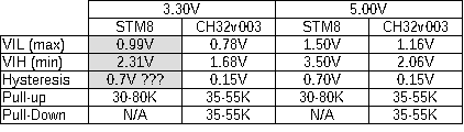
There are some GPIO input threshold differences between the STM8 and CH32V003.

I/O characteristics: STM8 has CMOS input threshold while CH32v003 has LVTTL threshold.

Note: Pull down resistors I normally use for push buttons on shared I/O needs to be below 8.9K.
3.3V * 8.9K /(8.9K + 30K) = 0.755V and 5V * 8.9K/(8.9K + 30K) = 1.144V

There are four 5V tolerant pins: PC1, PC2, PC5, PC6 (vs 2 in STM8) and up to 8 ADC pins. The alternate functions are more flexible as some can be mapped to additional GPIO pins. For the 20 pins package, Port C and D are rearranged as two contiguous 8-bit ports which make life easier for interfacing to byte-wise devices.

CH32V003F4P6 (TSSOP-20) GPIO pinout and their alternate functions

Bootloader

The chip doesn't have a Boot pin to select Bootloader externally. Instead there is a Mode bit that can be set to either jump to user code or bootload upon Reset.  SystemReset_StartMode(uint32_t Mode) under   
/EXAM/SRC/Peripheral/src/ch32v00x_flash.c in the application code example.


PlatformIO forum talks about how to modify the bootloader: here

Debricking


WCH-Link Utility menu - Full Chip Erase

Resources:

There is a bit-bang USB implementation available in beta - RV003USB  This implementation looks much cleaner than the STM8 VUSB project that I have been using.  The USB pins are configurable in usb_config.h 

There is a CH32V003 F4P6 V-USB Development Board with the USB pins on PA1 and PA2.

Alternate IDE:

Visual Studio Code using Platform IO plugin and Community-PIO-CH32V platform

Upgrade path

The next cheapest upgrade is the CH32X035 or CH32X033 marketed as USB Connectivity parts.  They aren't pin compatible, but they can operate at 5V with the improved RISC-V core, FLASH, SRAM, ADC, UART, USB.


CH32X033/035 features

RV32I – Base Integer Instruction Set, 32-bit. Currently version 2.1
M – Standard Extension for Integer Multiplication and Division
A – Standard Extension for Atomic Instructions
C – Standard Extension for Compressed Instructions

The most accessible parts are the X033F8P6 and X035F7P6 TSSOP20 parts with cheaply available breakout boards.  I have originally ordered the TSSOP and find myself maxing out the GPIO very quickly for a couple of projects I have in mind.  I have ordered some QSOP28 but cannot find a cheap source for breakout boards. QSOP has a pin pitch of 0.635mm (0.025") which is slightly tighter than the 0.65mm pitch for TSSOP20 which I can manage with my home made PCB. Their 0.4mm pitched QFN parts on the other hand would require commercial quality PCB.

The USB bootloader is activated by pulling up on the USB D+ pin at power on.


Sunday, April 7, 2024

The most uneventful WRT310N V2 8MB FLASH upgrade

 I bought this router at a thrift shop a long time ago for $5 mostly for its Gigabit Ethernet. It has been gathering dust as I have other ones with better specs.

Linksys WRT310N V2

Recently I need its 4MB FLASH for something else and my orders haven't came it.  I made a backup of the chip with my programmer.  3 months later, one of the orders finally showed up. I burnt a copy of the old 4MB image into a 8MB SPI FLASH: MX25L640EM2I.  It is important to keep the binary image of the chip as it contains some specific factory NVRAM settings e.g. MAC addresses that are not in the .trx file.

It boots up and showed 8MB in the status and managed to save a new setting. i.e. the FLASH chip is recognized.  I took a risk and upgrade to an image intended for 8MB device.  The worst that could happen is that I have to burn in a 4MB image and compile my own 8MB to support it.

It turns out that generic builds files with 32K NVRAM, MIPSR2 and without USB under the K26 directory works fine so far.  I picked the Max configuration with the full features set: 
freshtomato-K26-NVRAM32K_RT-MIPSR2-2023.1-Max.zip


It took about 90 seconds for the upgrade.  The most annoying part is to figure out the user name and password.  It took me quite a few tries as the username was changed to root from my previous firmware. Rest of it is uneventful.

It is good that the generic build recognizes the model as well as the correct FLASH size.

Status Overview showing router name and specs

Firmware version

Wednesday, March 13, 2024

The dreaded KB5034441 - what actually worked for me

Normally I don't talk much about fixing Windows problems as the tech blogs are a dime a dozen.  However, I have yet to find one that fixes the "0x80070643 - ERROR_INSTALL_FAILURE" with KB5034441. They seem all point to the WinRE partition wasn't sized sufficiently and each of them parroting the same stuff.  

I have resize the partition, but it still fails the update.  I have tried the PatchWinREScript_2004plus.ps1 from Microsoft, but it returned with a bunch of errors.  Obviously isn't fool proof enough for the end users.  I even ask Microsoft Copilot AI for a detail step by step instructions and it still isn't enough as there were errors in some of the steps.

I tried a whole bunch of things unsuccessfully and my WinRe was disabled.  I went through the usual long list of instructions trying to restore it manually e.g. extracting install.wim etc, but given up before I would do more damages. It is like a never ending quest like 50+ hours RPG with each quest requiring completing additional subtasks and no one have any up to date info.

What actually worked for me was to simply reinstall Windows. Obviously this is with the increased WinRe partition to 800MB and the install option of preserving the data and apps. This is the one with the least user interaction required, but no one else suggested this.

I let it install all the updates again and finally the dreaded KB installed properly. Whatever prerequisites that was broken along the way is now back to what they expect.  Don't forget to do a disk clean up for the old windows install and change back all your preferences that Windows like to muck with.

When in doubt, reinstall Windows.  :P


Sunday, January 21, 2024

CH341A Pro Serial PROM Programmer mods

The CH341A Pro Serial PROM Programmer is low cost programmer based on the CH341 USB Serial chip with special protocol modes for I2C and SPI.  A good source for the hardware info for the programmer is here

Some of the modifications are well documented on the eevblog. I cleaned up the mods and added a few.

Programmer modified for 3.3V

The programmer is modified for 3.3V I/O voltages as the ZIF socket is wired for 3.3V (see J3).

  • Vcc at pin 28 - connected to 3.3V (Required).  The CH431 chip I/O rail is set to the 3.3V supply from U1.

    Modification to PCB

    Side view of the modification

  • V3 at pin 9 - connected to 3.3V (Recommended by datasheet).  The internal 3.3V regulator for USB should be connected to the external source if Vcc is running from 3.3V.  I have measured the voltage at V3 and it is pretty closed to 3.3V, but modified it anyways as it is easy.
    V3 connected to metal tab of U1 - 3.3V regulator output


  • RN1C - connected to 3.3V (Optional).  The power LED (D1) is too bright because it is connected to 5V instead of 3.3V like D2.  The power LED now has similar brightness as D2.

Top trace: Resistor pack pull up that was connected to 5V
Bottom trace: 3.3V from U1 regulator

I have made a small plug for the programming cable using a protoboard.


I have replaced the spring for the clip-on programming cable as it is too strong and bent the pins on some of my chips.

Original spring (Bottom) is replaced with a weaker spring (top) from my junk box.