Projects / F103 Pod
32kHz oscillator start up issue
I ran into a bit of oscillator start up issue with the 32kHz crystal. I don't know if it is because of the corner cases of the cheap STM32F103 chips combined with the 32kHz crystal I pulled from a PC motherboard that doesn't satisfy ST's recommendation of load capacitance and bad luck. Looks like it could be VBAT is out of specs and that might have damaged the internal circuits in the process.Anyways the symptoms seems to be that from time to time the crystal would take a long time to start up and occasionally fails. My code was waiting for RCC_BDCR_LSERDY.

So I looked at the signal levels at the oscillator pins and found that PC15 (OSC32_OUT) was at 3.2V where as PC14 (OSC32_IN) was near 0V. There was something funny about this as there was supposed to be an internal feedback resistor that should make the inverter linear at about mid-rail.

I measured a DC resistance of about 2.8M to ground on both input and output pins. Not sure why it was grounded at the middle. Could that be a fault due to handling? Or that it was damaged by me violating the VBAT specs.
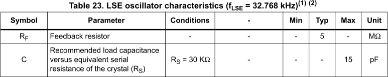
I read the following from an article (.pdf) They recommended 10-15M feedback resistor for 32kHz. Higher resistor values means higher gains.

I looked at a few of the PC motherboards and they all have a 1M resistor, so I have decided to take one from the motherboard and solder in parallel to the oscillator pins. It doesn't hurt if the oscillator passives are close to the values where I got the crystal from. I do however recommend to follow ST guideline whenever possible.
Both the pins are now at 1.6V and the start up issues seems to be cured for now. I have made the changes to the PCB layout for an optional resistor.
It seems like the VBAT circuit might be the cause of this issue. I used two silicon diodes to reduce the voltages from battery. In LTSpice, the voltage drop works out to be 0.6V at 1uA and in theory that should satisfy the maximum voltage.
I operate the board without the battery attached for development as I might need to solder or probe things. The LiPo charger is in float charge mode, so UB+ is always around 4.2V. With the battery attached, the charing would have been stopped and would not see voltages this high that often.

The problem is that the Power Switch circuit bypasses VBAT when VDD is present. There might not be sufficient current drawn to maintain a high enough voltage drop. I have decided to add an additional load at output of the diode with a 2.7M resistor.

LiPo capacity estimation
I have decided to estimate the MP3 player battery capacity by weight. I gathered a few LiPo batteries of the same pouch style from my collection. Unfortunately I don't have enough for a reliable estimate, but I think they are better than not having one.
The "400mAH" was a aftermarket replacement for the ipod mini. Apple had a recall of the ipod because of battery issues, so I swapped the my replacement back out. The "180mAH" one was from a picture frame and the two smaller ones are from 2 different models of the MP3 players. I trusted the "180mAH" battery capacity a bit more as it was a part in a product not directly sold from China.
It works out to be about 41.86mAH per gram. The battery weights which is mostly composed of the chemical ingredients are used as a ratio for the estimate. I think the numbers are close as the capacity are close to rounded numbers. The larger MP3 player battery is close to my initial 100mAH estimate.

The power consumption of the STM32F103 could be reduced by running at or below 12MHz while on battery.

No comments:
Post a Comment
Note: Only a member of this blog may post a comment.