 |
| My old alarm clock retrofitted with a STM8 |
This design is very similar to my other digital clock in
Part 1. This one uses larger common anode displays and requires higher currents (50mA vs 20mA). Each of the common anode digits is driven by a PNP transistor as they require more current than what the STM8 can source.
 |
| Display |
The driver and display are constructed on a protoboard using point to point wiring. I change their duty cycle via TIM4->ARR on the fly to balance the brightness for the last 2 digits.
 |
| STM8 breakout PCB + display drivers |
The alarm clock is power from a small 12VCT transformer. I have decided not to use the AC frequency for timing as the short term
accuracy is worse than a calibrated crystal.
 |
| Supercap backup |
A low ESR SuperCap is used to kept the time for a few minutes during a power failure or when I move the clock to a different AC outlet. The STM8 I use isn't a low power part. It draws around 2mA just to keep the RTC alive.
 |
| Piezo driver |
The alarm is a 1kHz tone from the Beeper peripheral with a simple circuit for driving the piezo buzzer.
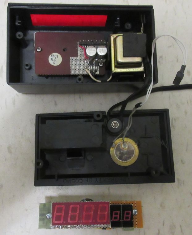 |
| Alarm clock assemblies |


No comments:
New comments are not allowed.