Search This Blog

Monday, March 8, 2021

STM8 Timer V2

 Go to Timer V1

Timer V2

There were a few changes to the V1 design.

  • Supercap backup power

  • Connectors for LED/sensor and Servo connector

  • Switcher module

  • LCD and buttons I/O changes. LCD backlight on/off control by ambient light

  • I2C connector

  • expansion connector for nRF24 (no firmware support)

Supercap backup power

Supercap backup

The backup circuit is similar to the one I have been using in my digital clocks.  I added the option of using a constant current source for charging the low ESR supercap. The resistor is simpler and have one less diode drop.

Servo connector

It turns out that the water pump I originally used wasn't reliable, so I have been using a servo driven valve.  I had to rerouted the control line for power supply the servo.  

Switcher module

5V supply

A DC-DC converter module is used for converting the 12V to 5V for the timer and servo.  I used a 10K resistor to set the output of the KIS-3R33 module to 5V.  Other modules can be used.

I am using power supply grade Tantalum capacitors as they take up less heights and offers a longer lifetime than electrolytic capacitors. The DC-DC module operates at 340kHz which helps to reduce the capacitance.

LCD and buttons I/O changes

I have decided to use time delay instead of polling for Busy Flag for the LCD.  This frees up 1 GPIO pin and simplifies the sharing of the LCD I/O signals for multiple functions.

Buttons

In the V1 design, an ADC channel is used for sensing the buttons.  The LCD data lines now are used for polling the buttons.

nRF24 module

Also new in this version is a connector for a nRF24 module.  The module uses SPI which shares the same data lines with the LCD. 

Timer with the nRF24 module

A bottom entry connector is used for flush mounting the nRF24 module.


github: https://github.com/FPGA-Computer/Timer

STM8 LED Clock - Part 3

Go to Part2

My old alarm clock retrofitted with a STM8

This design is very similar to my other digital clock in Part 1. This one uses larger common anode displays and requires higher currents (50mA vs 20mA). Each of the common anode digits is driven by a PNP transistor as they require more current than what the STM8 can source.

Display

The driver and display are constructed on a protoboard using point to point wiring. I change their duty cycle via TIM4->ARR on the fly to balance the brightness for the last 2 digits.

STM8 breakout PCB + display drivers

The alarm clock is power from a small 12VCT transformer.  I have decided not to use the AC frequency for timing as the short term accuracy is worse than a calibrated crystal.

Supercap backup

A low ESR SuperCap is used to kept the time for a few minutes during a power failure or when I move the clock to a different AC outlet.  The STM8 I use isn't a low power part. It draws around 2mA just to keep the RTC alive.
Piezo driver

The alarm is a 1kHz tone from the Beeper peripheral with a simple circuit for driving the piezo buzzer.


Alarm clock assemblies


Wednesday, April 8, 2020

Virus outbreak life hacks

Vegetables in 4-6 days, just add water

Growing bean sprout
While doing an inventory of my food supply, I came across some mung beans I bought about 10 years ago.  So I grew some bean sprouts from following this website. It is very nutritional and a low effort alternative for fresh vegetable during a food shortage.  I use the webbing from a pack of garlic to use as the mesh and tie it to the bottle with some solid wires.  I soaked the beans overnight and then rinse it twice a day.  Other than that, it requires very little efforts.  I had to stop after 4 days when the bottle was getting too full.

Stir fried noodles with bean sprouts
Here is one recipe for a stir fried noodle.

Egg noodles from scratch

Ingredients: 1 egg, 1/2 teaspoon of sodium carbonate, flour and water.
Tools: hands, pasta machine, measuring cup, flat surface e.g. baking pan.

Sodium carbonate (Na2CO3) can be made by heating sodium bicarbonate (NaHCO3).  It is also available as washing soda, however I don't know if they are food grade.

https://cooking.stackexchange.com/questions/9072/what-flour-and-technique-do-i-need-for-hand-pulled-noodles
Without sodium carbonate it's possible to have hand-pulled noodles with any flour. The downside is you will have to knead the dough for 45 minutes and leave to rest for 2 hours until you can start pulling your noodle strands.

The alkaline dough also help to discourage Salmonella, but hey you are going to boil the noodles at some point anyway.

1. Add 1 large egg, fill water to 1/2 mark, add 1/3 teaspoon of sodium carbonate.
Egg,, water and some sodium carbonate
2. Top it up the same measuring cup with white general purpose flour to a bit above the 2 cups mark. Why wash when you could use the same cup?
Add flour to same cup
3. Stir it around with a spoon until all the liquid is absorbed.
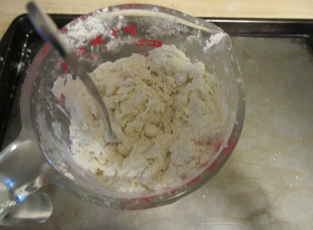
Stir a bit
4.  Pour contents into a surface.  I use a baking pan to contain spills. 
Lumpy mix from cup

5. Knead the dough until your hands  are clean.  It is a very tough dough, but it is a good exercise.
This is the time to stop
The clean up isn't too bad.  Leave the pan for now as you'll need it later.
Now it is time to clean the cup
6. Store the dough in a container and keep it in the fridge for about 3 hours and let it "rest".  Make sure you wash your hands after this as the dough is alkaline.  

7. I roll the dough with my manual pasta machine starting from the thickest setting.  I also trim the rugged edges and patch up holes in the dough.  Go one setting at a time to reduce the thickness of the dough sheets. Trim the length when the sheets gets too long.

This dough can be used for making wonton wrapping.

8. Cut the dough with the attachment.  Here is the finished product.I don't bother adding dry flour as the noodle is not sticky.

9. At this point you can put it in boiling water and it cooks in a minute.  Rinse under cold water to stops the cooking.  The noodle is very chewy.  Serves 4-6. The stir fried noodles was done with 1/4 of the dough.

10. I put it in a plastic container and freeze it.  I put a layer of food wrap between servings so that they don't freeze into one lump.  It take less than 2 minutes to cook in boiling water from frozen as there is no need for defrosting. 

Flat hook for DIY mask

I made a HKMask for personal protection.  I am not a arts and craft person, so I had to make do with what I have.  I modified the design as I don't have any thin elastic bands.  I do have a lot of fat ones from my grocery.

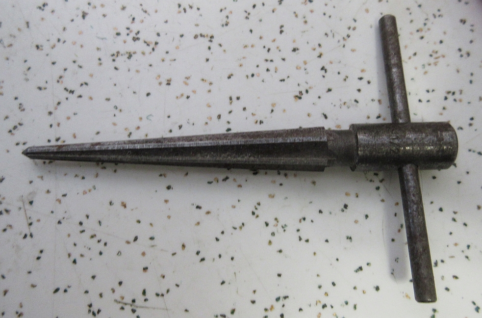
I use the I core from old transformer to make a flat hook and a AWG10 solid wire (household wiring) for the loop. The rubber band is very strong, so it is important to have the right cord lengths for comfort and fit. I crimped the 2mm paracord gently during length adjustment.  Once the adjustment is done, I crimped tightly to hold it in place.

DIY flat hook
Hook material: stamped I/O bracket cover for a cheap PC case or transformer cores

Monday, March 16, 2020

STM8 Timer - servo controlled water valve

The motor in the submersible pump I was using has started to rusting after a year and a few months. The rust stops the motor from spinning until I hit it with a high enough voltage which eventually exceeded the power supply I was using.
Pump motor is rusting
I ordered a couple of replacement pumps, but they are probably stopped somewhere between China and the post office due to the virus.  I have decided to go for a different approach.

I  made a servo controlled valve to control the water flow from a siphon.  This simplifies the overall design by removing the pump at the source and reduced the wring needed.
Top view of assembly
I used a Tower S9 micro servo mounted in a cut out dental floss case with a couple of M2 screws.  I used a cheap metal air valve, but it seems to work okay so far for water.  It is held down with 3 L shaped bracket with a couple of screws. The brackets are made out of the left over bits from the case. The servo arm is coupled to the handle with a 'g' shaped metal strip from a transformer.  The valve side is loose enough to allowed it to move to accommodate for minor misalignment.

Side view of the assembly
Two large holes are drill on the side of the case for connecting the tubing.

Timer Aux power supply 
There are a few modifications needed on my timer project for driving the servo.

  • R2 is replaced by 2.7K while R7 is replaced by 8.2K.  This sets the output to 5V
  • D3 is removed. The 5V output on J4B is now always on.
  • J6 is installed.  The /EN signal is used for driving the servo
/EN (PD3) is used as PWM for driving the servo
The 5V, GND, PWM signal are routed to a 3-pin connector for the servo.

I used TIM2 for generating a 50Hz PWM signal for controlling the servo.  TIM2 is disabled after 1 second when the servo is in the "Off" position.  This powers down the servo and prevents the annoying rattling in some cheap servos.

Monday, January 27, 2020

Fixing my Weller WESD51 soldering iron - quality not found

I went to the only local electronic part store eons ago to buy replacement part for my older soldering iron. It was a decent iron that lasted such a long time that the store no longer carry the replacement parts.  I bought the WESD51 as it was on a back to school sale and Wellers parts and accessories was easier to find. It was a lemon. Ironically the serial number happens to be 0404 (Quality not found!?)

4 hidden screws under the rubber feet
Right from the start I had a lot of issues with the iron not reading its temperatures correctly. I thought it was a connector issue, but later I found that it was a manufacturing quality problem.  They change a PTC fuse into a larger package (green 2X2 at top of PCB) but didn't do a good job of touching up the soldering on the mismatched footprint.  So I had to fix it up in the first few months.

Control PCB
A trimpot has limited cycles, so personally I wouldn't use it for a temperature control knob. It did last a very long time, but obviously not long enough vs the rest of the iron.  A few months ago,  the temperature setting started jumping beyond my set point due to wiper contact issues. I knew I had to repair it.

PCB back side
As I was opening it up, I found out that they didn't do a proper crimping job on the AC leads of the power transformer as they tried to crimp a tinned wire instead of bare wires!?  Solder is soft, so eventually the wire came loose.

Poor crimp job
Here is the cheese knob for the trimpot.  It was held together with a self tapping screw. I had to put in some hot glue to hold the screw.

Cheap plastic knob for the temperature control
 I ordered the smallest 10K linear potentiometer I can find and they arrived today.  I couldn't find any 2K pots.  Since it is to provide a 0V to Vcc to the ADC. The increase in source impedance could affect the ADC result. One way to fix it it to wire a 0.1uF cap from wiper to Gnd, but that is not needed here.

They are not the greatest quality, but I got a bag of 5 for cheap. They came with washer and a nut.  I use a pencil to trace the outline of the washer on the PCB and milled out a notch for the locating pin.

Modification to the PCB
I mounted the pot onto the PCB and soldered the pins to the existing pads with wires.
Pot connections
I had to remove a bit of the material in front case to clear the mounting hardware for the pot.

Making room for the mounting hardware
I use a reamer to enlarge the hole, so that the PCB can be mounted flush.

Old Radio Shack reamer
It ain't pretty as it is soft plastic. The hole is hidden away by the knob.  The shaft is barely long enough.

The big hole I made
I broke off the cheesy plastic off the knob.  I got some cheap plastic knob from China that is small enough to fit inside the cavity.

Temperature control knob
It wasn't tall enough nor wide enough, so I had to improvise.  I melted about 1/2" of hot glue stick with my hot air tool set at 120C in the cavity.

Hot glue to the rescue
I pushed the plastic knob into the molten hot glue and wait for it to set.  I filed down the knob so that it is flush.  I added some extra hot glue for support on the sides as well.

Improvised knob
One of the things I did to prevent the plastic mounting post from splitting was to use a piece of cable around it.  I wish they would use threaded inserts.