 Projects / PC Mods
I am doing some rewire on an old PC. The existing chassis fan doesn't have a techometric output, so it's time for some hacking.
They use a Hall Effect sensor for sensing and driving the 4 poles 2 phase
BLDC motor. L1 and L2 are driven at 180 degrees out of phase.
I have seen cheap fans with a single schottky diode to replace the transistor + resistors. I would prefer the transistor as the failure mode of a diode is a dead short while the transistor circuit is inherent safe.
There are footprints for the missing parts on the PCB - Q1, R5 and R4. I use a small signal NPN from my junk box. (e.g. 2N3904 would work) and a 4.7K for R5 and 10K for R4. It is nice of them to label the transistor pins as it is a different style of pin out.
The circuit sense the voltage at one of the windings with a transistor. When the driver is off, the transistor see 12V and pulls its output low. The output is open collector. It is level shifted on the PC motherboard side with a pull it up to I/O voltages (3.3V in mine).
I have to shuffle the transistor (Q1) pins to line up with their footprint. I don't have the small sized resistors, so I use some surface mount 0805 resistors. The "S" (white wire) is the Tack output which is open collector.
This is what the waveform looks like with a 10K pull up to around 2V from my DMM diode test.
I wired it up to a 3 pin connector and plugged into a chassis fan header. It works!
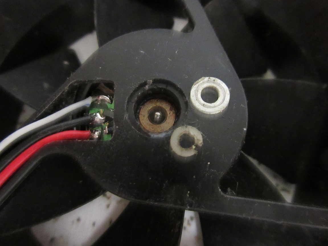
I modded a really old Panaflo fan. This was from the PC/XT clone power supply. The fan has a pair of ball bearings and a planar spring to take up slacks in the Z axis. This was really well engineered. Usually old PC fans with bronze brushings rattle because they develope slack over time.
It was built with discrete parts - hall effect switch and transistors. There is a diode connected in series at the ground return side for reverse polarity protection.
The same circuit also works well with this. (The schottky diode trick won't work here.) The emitter of the transistor circuit is connected to the negative terminal before the diode as the PC side expect to see a 'L' signal (less than a diode drop. ) The threshold of the transistor circuit is about 1.8V, so it can handle the extra diode drop.
Modded another fan. This time there are no place on the PCB for mounting the parts.
I cut up the traces on the PCB to make room for SMT parts. I scrapped off the solder mask for the pads and tinned the exposed copper.
The SMT parts are soldered in. I have to flip the transistor to swap the base and emitter to match the existing traces.
Usually these cheap fans last about 3-6 months before they start making noise. I put in a washer to take up the slack in the shaft a long time ago because of that.


No comments:
Post a Comment
Note: Only a member of this blog may post a comment.