 Component Tester
based on design from svn://mikrocontroller.net/transistortester/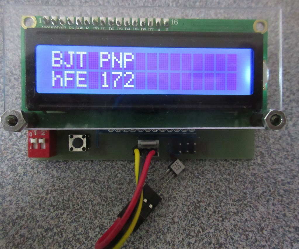
I needed a ESR meter for fixing a failing PSU with possibly bad capacitor(s). I came across the Transistor Tester project on mikrocontroller.net. It seems to be a decent design with lots of features and most importantly good documentation. Here is the Hackaday review for these clones:
I have decided to add a few of my personal touches to the design instead of buying a Chinese clone.
Github of the original project : https://github.com/svn2github/transistortester
Instead of buying one from China, I have decided to make my own using the parts I have.
- A boost mode power supply for operating from 1 AA NiMH battery at about 45mA.
- 16x2 characters LCD module with backlight High/low setting
- Power On/Off switch
- I/O mapping is based on Markus's version with the following exceptions:
- ATMega328 in TQFP with 2.5V reference at ADC6 and Battery voltage at ADC
- 7PC3 - PC5 are unused and are available on connector JP2

Power Circuits
This design simplifies the power control circuit from the original design.
At power off, the /SHDN pin is pull down to 0V via resistors R4, R6. This put the boost converter in shutdown mode and should be drawing less than 1uA of current (typ). SW1 can be used to disconnect the battery.
This converter internally disconnects the Vout, so no need for external shutoff circuits.
When the push button S1 is pressed, the /SHDN pin is raised to the battery voltage. This enables the boost converter and Vout is at 5V.
There is a conductive path from the ADC input ESD protection diode(s) to the VCC rail. Q1 is used to isolate the battery supply voltage from the ADC input when the microcontroller s supposed to b powered down. Gate of Q1 is connected to the VCC and when it is raised above the VGS threshold of the battery voltage, it turns on connecting the ADC input.
At some point, the microcontroller wakes up and set PD6 to a logic '1' to latches the power on. The microcontroller can power itself off by setting PD6 to logic '0'. R2 is there to protect and override PD6 when S1 is pressed while the microcontroller tries to power down by setting PD6 to '0'.

Don't blindly believe that "5V" logic parts needs 5V inputs, read the datasheet: (Vcc=5V)
Logic '0' threshold: VIL(max) = 0.3*Vcc = 1.5V
Logic '1' threshold: VIH(min) = 0.6*Vcc = 3.0V

The feedback resistor values for the power supply can be calculated as follows

Vout = 5V; VFB = 1.21V for MCP1640. I pick Rbot = 15K
Rtop = 15K * (5.0/1.21 - 1) = 46.98K Closest value is 47K
Limitations of this tester:
- There are no input protections. Make sure that capacitors are discharged prior to testing.
- Inductance measurement has a minimum of around 5uH
- For low value capacitors, their ESR measurement is dominated by their impedance at low frequency.
Project files are under "Transistor Tester" in my github This is under CC BY 4.0 license.
Boost Supply
Did I tell you that I dislike "designs" that use 9V battery because they are the most over priced batteries on a price/unit weight, do not have much capacity and people are throwing away nearly half the efficiency by using 7805 linear regulator?
The MCP1640 is supposed to be able to source up to 100mA at Vin = 1.2V.

ATMega168 active current is supposed to be 9mA at 16MHz from 5V. The current can be reduce somewhat by using the prescaler to reduce clock speed to 8MHz or 1MHz.
I could also drop the LCD backlight down or use one without backlight.

The description for alternative boost converter without disconnect is preserved below for historical reasons just in case someone might want to hack a $0.50 USB voltage booster instead.
Firmware
Working with Markus branch: transistortester-master/Software/Markus/ComponentTester-1.31m.tgz
The code is mostly in C and a lot cleaner. I am trying to set it up as is without Makefile. It is not throwing warning messages like the trunk is. The only possibly gotcha is that I am using a ATMega168 and won't not have the memory for the code. I have to see what features I need to trim off fit.

The main trunk supports smaller devices. I might have to replace some of the C files with the ones in assembly language from the trunk.
I order the 328 version module just in case. Have to be careful as there are slightly different pinout version just enough to require a different layout.
Markus firmware customization
This branch have the necessary hooks for changing ADC. These changes let me set aside the more flexible PC3-PC5 as spares.
config.h

I made some changes to the source code to divide the 16MHz to 8MHz using the clock divider to reduce power consumption.
In main() in main.c:

config.h:

In main() in main.c:
config.h:
Power consumption is around 50mA (idle) to 70mA. So for a healthy NiMH battery, that's about 30+ hours of battery life.
ADC7 sense the battery voltage without a voltage divider and the MOSFET has no DC offset. Battery low/weak is set for NiMH type.
config.h:
I redid the layout as I didn't like the issues with the through hole pads.
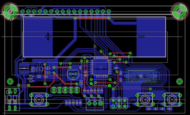
All soldered up:

I have moved the ATMega328 onto the PCB and replaced the 16MHz crystal with a 8MHz crystal. I added the optional Inc/Dec buttons which would be useful for some of the optional features.


To enable the IR and the new mapping, uncomment the SW_IR_REEIVER and define SW_IR_ALT_PIN.
config.h
In IR.c: (This deals with the LCD message)
This deals with the actual pinouts. It powers the IR receiver by using the I/O pins to 'H' or 'L' or through a series resistor. References to TP1/TP2 and R_RL1/R_RL2 are swapped.

I soldered a socket to socket dongle so that I can plug th module into the test connector as is.ADC7 sense the battery voltage without a voltage divider and the MOSFET has no DC offset. Battery low/weak is set for NiMH type.
config.h:
/*
 *  Voltage divider for battery monitoring
 *  - BAT_R1: top resistor in Ohms
 *  - BAT_R2: bottom resistor in Ohms
 *  - for a direct measurement without a voltage divider set
 *    BAT_R1 to 0 and BAT_R1 to 1
 */

//#define BAT_R1           10000
//#define BAT_R2           3300

#define BAT_R1           0
#define BAT_R2           1

/*
 *  Voltage drop by reverse voltage protection diode and power management
 *  transistor (in mV):
 *  - Schottky diode about 200mV / PNP BJT about 100mV.
 *  - Get your DMM and measure the voltage drop!
 *  - Could be also used to compensate any offset by the voltage divider
 *    used to measure the battery voltage.
 */

#define BAT_OFFSET       0

/*
 *  Battery weak voltage (in mV).
 *  - Tester warns if BAT_WEAK is reached.
 *  - Voltage drop (BAT_OUT) is considered in calculation.
 */

#define BAT_WEAK         1150

/*
 *  Battery low voltage (in mV).
 *  - Tester powers off if BAT_LOW is reached.
 *  - Voltage drop (BAT_OUT) is considered in calculation.
 */

#define BAT_LOW          1050
I redid the layout as I didn't like the issues with the through hole pads.

All soldered up:

I have moved the ATMega328 onto the PCB and replaced the 16MHz crystal with a 8MHz crystal. I added the optional Inc/Dec buttons which would be useful for some of the optional features.

Now that all components are mounted on the back, the LCD is mounted flushed onto the PCB. This drops the height profile a lot. I used individual stranded wires to connect the LCD. This reduces some of the stress on the pads.
 IR receiver

There is an option for enabling IR receiver on the probe (under the menu). I have modified the pinout in the firmware so that it lines with the Chinese IR chip.
config.h
/*
 *  IR remote control detection/decoder
 *  - requires IR receiver module, e.g. TSOP series
 *  - module will be connected to probe leads
 *  - uncomment to enable
 */

#define SW_IR_RECEIVER

// Alternative IR Pinout 1: Vcc, 2: Gnd, 3: Data
#define SW_IR_ALT_PIN
In IR.c: (This deals with the LCD message)
  #ifdef SW_IR_RECEIVER
    LCD_NextLine();

    #ifdef SW_IR_ALT_PIN
    /* display module pinout (1: Gnd / 2: Vcc / 3: Data) */
    Show_SimplePinout('+', '-', 'd');
    #else
    /* display module pinout (1: Gnd / 2: Vcc / 3: Data) */
    Show_SimplePinout('-', '+', 'd');
    #endif
  #endif
This deals with the actual pinouts. It powers the IR receiver by using the I/O pins to 'H' or 'L' or through a series resistor. References to TP1/TP2 and R_RL1/R_RL2 are swapped.

IR detection can decode some of the common IR code. It is however a bit glitchy and often detects the wrong protocol. I hope that could be fixed in some future firmware update.

Github: https://github.com/FPGA-Computer/component_tester
No comments:
Post a Comment
Note: Only a member of this blog may post a comment.