Projects / F103 Pod
Original post date:12/15/2017
One MP3 player arrived today. The LCD doesn't have the ugly yellow/blue filter from the description.
The plastic case is held together with 4 tabs near each of the corners and 2 on each end. I broke all of 4 corners tabs when I pried it opened with a knife. I think I'll have better luck with the 2nd batch from a different supplier as they are supposed to have screws and come with belt clip.
The PCB thickness is 0.026" (0.6mm). The stereo connector (0.2") and the LCD (0.086") are the tallest components on each side of the PCB.
The battery is a LiPo pack without any protection circuits nor a proper charger chips. There is a silicon diode (CD1) in series from the VUSB as the charge circuit.
VUSB has a loose tolerance of 4.4V to 5.25V while a silicon diode drop is around 0.7V, so you might be charging the LiPO with up to 4.55V! There are no current limiting other than the internal resistance of the USB cable, LiPO and power source. What can possibly go wrong? (Cue Mission Impossible OP).
The battery ( 0.831" x 0.860" x 0.113") is held above the Micro SD connector with a piece of double sided tape. I estimate the battery capacity to be around 100mAHr based on size.
The LCD and the dome buttons are on the back side of the PCB. The Red/Blue wires are the LCD backlight. I measured 2.85V. It is driven directly from pin 16 of the chip without a series resistor.
he back side of the LCD diffuser is taped to the PCB with a piece of double sided tape. There are two sets of footprints to accommodate modules with different cable lengths.
PCB high resolution scans
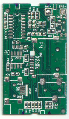
I made a couple of high resolution (2400DPI) scans of the bare PCB with my flatbed scanner. I am going to be using the scans for the measurements. I'll have to wait for the second batch from the different supplier.
 |
| Component side (Click for full resolution) |
 |
| Top side (Click for full resolution) |
- The standoff keepout areas are marked with a Sharpie. They are in different location than the silkscreen.
- Two of the pins covered by silk screen are not connected. They are probably using I2C mode to access the MicroSD.
- One of the Mini-USB non-plated through holes encroaches into the "Next" button pad. I'll resize the hole to try to minimize the effects and also might have to play around with the DRC to reduce the void.
I imported the bitmap into Eagle CAD and overlay it on top on the layout template from github and there seems to be a lot of discrepancies on the placements.
As I have learnt many times before, most of the freebies from someone else ended up costing me a lot. I will be doing my own from scratch.
This is what the layout should look like. The scanned image has the right X/Y scaling and aligns with the placement holes.
This is what I have done:
- measure the PCB with a caliper
- (previously done) rotate the scan to align with X/Y axis
- reduce colour depth to 4. This make things goes faster while retaining details.
- import into Eagle PCB as .BMP and 2400DPI
- overlay measured board outline and main components
I found another discrepancy of the the SJ-2523 stereo connector footprint used. According to the datasheet, the spacing between pin 1 and 2 should be 11.4 -1.7 = 9.7mm (0.382")
Well... It is 0.275" for the part I pulled from the MP3 player.
I guess I should have checked the component side of the layout myself and not give any blind trust to someone else's. The rest of the components seems to be fine.
I imported the scan into Visio and to draw some rectangles over them as a quick and dirty way of measuring the distances. I measured the distances of the pads to the alignment holes to figure out the X offsets. The X, Y scaling factor are computed from the component outline vs actual measurements from my calipers. The offsets are rounded to 1/10 of a mm for the footprint.
The footprint were a bit off to start out with, so this isn't going to be as good as one made directly from the manufacturer's CAD drawing. It is close enough.
Teardown of 2nd MP3 player
The 2nd batch of MP3 players arrived via Kyrgyzstan. Canada Post have decided to raise the postage fee from China Post starting from 2018, so I would expect to see a lot more creative logistic shipping routes in the future. Canada Post service has deteriorated over the past few years.
Two pegs from the panel latches down the button wheel. The button wheel can then be popped out from the front.
The PCB assembly slides out from the right hand side.
It uses the same PCB design as before. The LiPo pack is about half the size ~50mAHr. The overall build quality is slightly better.
Some of the cheaper PCB house only have silkscreen on the top layer which is on the back side of the PCB. The LCD position no longer lines up with the silkscreen as it is shifted lower to accommodate the curvature of the case.


No comments:
Post a Comment
Note: Only a member of this blog may post a comment.