
Projects /
Original post date:07/31/2014
This is an old hack that I did years ago. These days, you can buy Altera USB Blaster clones for less than $3.
 I want to start playing with Altera FPGA software, but my old Byte Blaster parallel port dongle won't install under Windows x64.I dusting off my old project and make my USB Blaster clone. This is slow, but not a couple of weeks waiting for a $6 clone arriving from China slow. So this will be my back up plan if the dongle DOA or come in late.This is designed around a TI TUSB3410 USB to Serial chip which TI uses in their programming dongles for the MSP430 series. This was also popular in earlier mobile phone serial interface dongles until cheaper chips like PL2303 clones flooded the market.It has a non-enhanced 8052 core running at 2 mega cycle/sec (24MHz/12) and requires multiple cycles per instruction.This was a demo for the TUSB stack. It is as mongrel as it can be and it shows the power of Open Source very nicely.Source code:

Micah Dowty wrote the pure polling USB code which I changed into interrupt + polling using 3-4 of TI App notes and use header file from libusb for the data structure. I strip off most of TI's callback functions that are hard to understand. The resulting code works kind of like V-USB and work well under SDCC.
USB_JTAG:
The hight level code came from ixo.de : http://ixo-jtag.sourceforge.net/#usb_jtag
usb_jtag project that uses Cypress FX2 which is a modern day 48MHz 8051 chip. The code was nicely optimized and with machine code for the 8051. I changed the low level GPIO bit banging code and grafted the high level code on to my USB stack.
USB Blaster:
The USB_JTAG code there was ported over to Microchip on this Japanese page: http://sa89a.net/mp.cgi/ele/ub.htm for making the Altera USB Blaster clone.
I ported the EEPROM code and USB descriptor code which are critical for cloning Altera USB Blaster back.
Hardware:
TUSB3410 connection - bus powered

Power supply and EEPROM (not actually used)

Level Translation:

Level Translation:
VIO is the I/O voltage of the target. It comes in via series resistor R20 to power the level translation circuits. Q5 is a shunt regulator. It clamps down the I/O rail to limit the voltage to about 3.4V if you connect VIO to say a 5V system.
Note: U1 has an absolute maximum suply voltage of 6.5V, it is only spec for up to 3.6V for normal operation.
For the signals going out of PCB, it passes through U1 which acts as a level translator. If my target operates on 1.8V, U1 would be on a 1.8V power supply and its output would be between 0V to 1.8V. The 74LVC series is great for that as its logic input can exceed the power supply voltage. There are series terminating resistors on the output to reduce signal reflection as the dingle is usually connected to a target using loose wires.
Note: 74LVC part is very fast and they require terminating resistors if your track is longer than about 0.5 inches!
Now what about the extra bits of transistors circuits?
Q4 (in Cascode topology) is a level translation circuit that convert the incoming TDO back to 3.3V for the TUSB3410. The capacitor C7 is for compensating for Miller capacitance that would otherwise slow down the circuit.
Q2 & Q3 forms a bidirectional level translation for the TMS/SDWIO. (SWDIO and SWDCLK are for ARM debugging not needed for USB Blaster Clone)
Jim Hagerman wrote a paper "Two Transistors Form Bidirectional Level Translator"
www.hagtech.com/pdf/translator.pdf
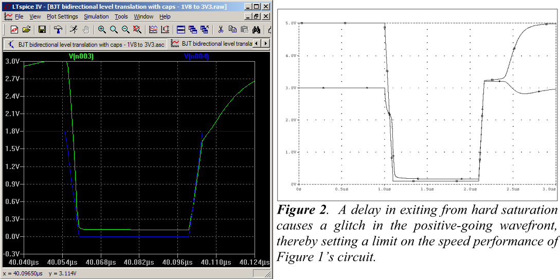
" Tests show that the circuit operates easily up to 300kHz. The major impediment to fast operation is the delay that occurs when Q1 comes out of saturation on a rising edge."
I played around with the circuit in LTSpice and figured out how to improve the performance by adding a couple of capacitors that speeds up the discharging of the Miller capacitance that caused the slow down.
(My LTSpice circuit on left)

LTSpice plot: Blue: 1.8V input, Green: 3.3V output.
I played with the pull up values to improve the rise time. Notice that the delay is gone as the capacitor C1 discharged the Miller capacitance. By the way, my simulation is for 10MHz!
This is how it looks like translating from 3.3V down to 1.8V

How is this useful vs the usual ones built with MOSFET circulating on the Internet?
e.g. 2N7002 has Vgs threshold of: 0.8V (min), 2.1V (typ) and 3V (max).
You'll have a bit of trouble using that part with that wide spread of a range of a threshold for level translation. The BJT transistors have a input threshold of around 0.7V with a much smaller spread, so it can easily work down to 1.x volt range and not limited for 3.3V. I/O voltages are going down these days and 3.3V is only the first stop.
This is just here to show that discrete bidirectional level translation can be done using discrete parts that I have lying around. For any logic translation, I would not recommend this circuit as it has a very high input capacitance that would load your circuit at high frequency. There are much better bi-direction translation chips these days.
I also would not recommend this for I2C translation as this circuit does not work on open drain signals as my pull up is too small for that and the extra capacitance would make the signals looks worse. Jim Hagerman's design uses 10K pullup and probably has that in mind.
Newer design (see epilogue):

Here is the level translation circuit I used in a more recent design. I deciphered the part markings and found some 74CBT1G125 parts that I can recycle.
Normally these 74CBT series are designed for 5V to 3.3V level translations, but there is a way to hack it. In one of the app note, "Table 3. Possible Voltage-Translation Combinations Using a TVC Device", TI left a bit of cookie crumbs in the bracket.


So what is inside one of these TVC? It is simply a array of MOSFET that have their gates tied together. What's so special about that vs discrete parts? Since these transistors are on the same chip, their properties are very closely matched and they have the same temperature.
One of the transistors is (A1/B1) that is used as a shunt regulator to set a reference voltage at "GATE" to Vt+VREF. If there are any process variations, this arrangement will cancel out the differences as the GATE voltage is tracking Vt.
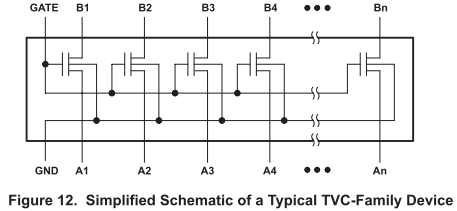
Now what can I do for mine? If I tie /OE to ground, the inverter would connect the GATE to the supply rail making the three connection available. Since the /OE signal doesn't change, I can assume that as long as my supply voltage is higher than Vt, that the inverter would operate statically as it should be.

I made some assumptions that the threshold voltages of these parts are probably below 1V (see hint 2) and may be with a spread of 20% due to process/temperature variations.

For my application, I set my GATE about 1.1V above the VIO and if I do see that extra few hundred mV isn't going to bother my TUSB3410 much.
I'll try to post the files up somewhere once I figure how to do so and get the code cleaned up.
Now why was I interested in bidirectional level translation? I was planning ahead for ARM SWD debugging when I initially designed the circuit. That's another story.
Epilogue
Recently, I built a new rev. using ATMega8 with the proper level translation chip for CMSIS DAP and hope to use V-USB. Unfortunately the CMSIS DAP code insists on using a large fixed sized interrupt transfer for HID and there is where V-USB breaks. First off the USB standards increased the interrupt intervals from 1ms to 10ms and only allow 8 byte packets for interrupt transfer. There was no other way to send more than that either.I rewrote part of the TI USB stack to handle the interrupt transfer needed for HID and got it partially talking to the debugger. It was funny to see that the much slow TUSB chip chucking along as it has USB hardware and not limited by that. The lower level stuff was mostly written for ARM, so porting wasn't going well. Also I don't want to actually debug that stuff. I am shelving that until I can find some $1 ARM chip. Now that's for a different project.
OpenOCD went overboard with their code allowing accepting only FTDI devices, so I no longer interested in this nor their code base.
My code is on github: here
No comments:
Post a Comment
Note: Only a member of this blog may post a comment.