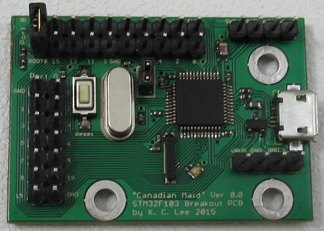
I bought some STM32F103 a couple of years ago and had been procrastinating on using them. You know the usual excuses: can't make the PCB, compiler toolchain is hard to setup etc.
Now I have unused board space for a Chinese PCB batch for a job, so it is time for a speedrun for a breakout board filler. Plain breakout boards are no brainer, so that why they are perfect for these.
This is also a not so serious attempt for me to not read the datasheet in detail. What can possibly go wrong? Will this be ended up being a Fail of the Week post? Stay tuned.
SMT alert: 0402 and other small parts.
Not competing with $2 Chinese clones as they can sell it including shipping far cheaper than me asking for shipping while giving it for free. https://www.aliexpress.com/wholesale?catId=0&initiative_id=SB_20180807105855&SearchText=stm32f103c8t6+board
Here is where you can find Arduino for it if you are into that type of thing.
https://www.hackster.io/rayburne/maple-mini-clone-update
https://github.com/rogerclarkmelbourne/Arduino_STM32/wiki
https://github.com/MakerLabMe/STM32_Arduino_Cores
http://www.stm32duino.com/
Project files for my initial PCB built is on my Github directory I have cleaned up the layout a tiny bit.
I need to fill a last minute board. That was 6:30 pm last night. Between dinner and layout, etc I had it mostly (99%) done just before I went to bed at 1:15am. Now I have to play around a bit with the board outline etc. I guess I am kinda late as it is Saturday in China.
The board came out a bit cleaner than I thought it would be. I managed to untangle the I/O ports so that they are ordered to their bit ordering instead of the pin numbering. The break out is designed for IDC cables and the usual "Dupont" loose wires cables from China should fit quite well too.
Force of habit, I try to maintain as much ground plane as I can and bridges the discontinuities the best I can. That is something not often done enough for Open Source work.
The usual 3D money shot! Usually I do this before ordering the PCB, but this is a speedrun. Good luck pressing that reset button without poking your fingers out!
Not too bad for something that I throw together in less than 24 hours.
They updated my order with the one that has the text on the correct layers. This was received on Saturday 4th July while some of us are still recovering from Canada Day and other Southern neighbours are celebrating their Independence Day.
And they have to mess up the custom value declaration again and ignore my explicit instruction to not to include shipping charges into the value. It is DHL, so there are no cheap way of getting around it. This is for work so I use the more expensive shipping option. The postal system is unpredictable and slower, but does offer refund if I can show corrected paper work.
$15 to DHL to refile the paper and possibility of bumping the shipment out to next week. (Friday today)
Pay the $21 or so for their mistakes and hope to get the supplier to refund. Ha! They haven't even reply to my email on their their shipment custom value declaration mess up.
I think I baked it a bit too much. Still trying to get used to the new hot air tool. It is a bit too bulk to hold and can blow off the small parts easily.
There was something fishy about initial power up. Might ave been a short or something. Once I desoldered the LDO and hooked up my bench supply with current limits, it powers up. Soldered back the LDO. Current is about 11mA. Sounds reasonable.
I'll leave the testing for another day as I am behind my schedules.
So looks like I might have missed the USB pull up. Pretty much most of the microcontrollers I have used have internal pullups for the USB data pins, so I don't usually think about that. The quick fix is to connect a 1.5K between PA15 and one of the USB data lines depending on the connection speeds.
Another possibility is to have a permanent 1.5K pull up on D+ to 3.3V like V-USB. The USB pins can be mapped back to GPIO and the D+ pin can be driven to logic "0" to fake a disconnect.
Blinky LED - first sign of life
I have managed to compile ChibiOS 3.0.0 for the STM32F103 using the modified Maple Mini files. I got a blinking LED running in a Thread, so the base RTOS is working.
There is something funny about the UART serial driver not initializing correctly and cause an exception error. I haven't spent much time on that as I merely copying the high level init code from my FPGA board.
Okay. That was embarrassing. The demo code was using a different driver "object" SDU1 instead of SD1 that I have initialized. So a NULL reference to SDU1 caused an exception error. Now I have to hunt down the baud rate setting. Not sure how I soldered in a 10MHz crystal instead of 12MHz.
The demo code with a simple shell is running.
Test setup:
UART1: Port A - GPIO 9: TxD, GPIO 10: RxD
Upper left Jumper: Installed = run, Not installed = STM32F boot loader.
Upper left corner: USB - Serial dongle
Upper right: SWD connector to debugger (PA13, PA14 GPIO pins are used as SWD.)
I ported my Noka 5110 LCD driver code to the board. This is using the STM32F103 SPI1. I am using the polling call as DMA overhead might be a bit too much for transferring very small blocks of data. I am going to do more coding to turn it into a ChibiOS stream device for chprintf().
Github file: here


No comments:
Post a Comment
Note: Only a member of this blog may post a comment.