I did some quick tests with the old PS/2 keyboards I have.
I wired up the following test circuit for testing.
 |
| PS/2 test schematic |
- added a LM1117-3.3V regulator. This is old chip design that has a high quiescent current and it doesn't like ceramic output cap. On the other hand, I paid $0.04 (QTY 10) from China and my old PS/2 keyboards aren't exactly low power consumptions (~110mA).
- The bootstrap mode only support PA9/PA10, so they are going to be used as serial port pins. I would have used these for PS/2 as the are 5V tolerant. PA0/PA1 are the ones with the least amount of alternate peripheral functions, so I use them as PS/2 keyboard.
- The PS/2 signals are supposed to be TTL bidirectional "open collector". The lower voltage threshold is typically 0.7V. With the 3.6mA short circuit (to ground) current pretty much put an upper limit of around 200R on the series resistors R5, R7. 3.3V meets the logic high minimum threshold (VIH) for TTL signal. It works for all the keyboards I have.
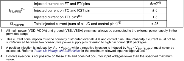
- The short circuit current (to 3.3V) is 1.6mA, so that's within the +/-5mA max injection current on the STM32F0 pins and I could get away without additional parts. I would feel a bit better to at least put some level of overvoltage protections as keyboard is at the long end of a cable and might pick up spikes or ESD. I ordered 50 zeners from China and I won't expect to see them for another 45+ days if I am lucky. For the time being, I'll use the 4.7K pull down resistors for 3.3V conversion.
- Update: I have switched to Schottky diode clamps as the Zener diodes drops the logic high of the open collector signals to 2.8V reducing noise margins.
 |
| STM32F030 I/O maximum rating |
This is what the circuit looks like on a breadboard.
 |
| ChibiTerm prototype - with PS/2 |
I ported some of my low level PS/2 from my FPGA project. I have to rewrite the code that relies on message passing, time out and tasks into bare metal. Also ported my set of print routines for debugging.
 |
| PS/2 raw scan code captured to terminal |
☑ I can now receive the raw PS/2 code correctly.
Next on the list is to debug sending PS/2 code to the keyboard.
 |
| PS/2 timing diagram (from logic analyzer) - commands sent to keyboard |
☑ I can now send the raw PS/2 code correctly.
F2: Read keyboard ID
returns: 0xFA = ACK for the command, (0xAB ,0x83) = MF2 keyboard
Reference: http://wiki.osdev.org/PS/2_Keyboard
Also ported my small debug shell to this. It makes debugging a bit easier to be able to call up routines.
Quite ironic that the Pause key seems to crash the firmware. It is a special key that generates a long string of key code. E1,14,77, E1, F0,14, F0,77
Looks like more work needs to be done in my ps2 code. This code sequence confuses a lot of my code as the key codes 0x14 and 0x17 also maps to [Control], [Num Lock].
 |
| Capturing the buggy scancode sequence |
So looks the easiest is for me to trap the sequence before it gets to the upper level. I'll probably use a separate state machine as this code sequence is highly irregular.
Here is what I have. There are 3 states to catch the two sequences that starts with 0xE1
case PS2_KBD_RDY:
  // extra code to intercept Pause key code
  switch(PS2_Fsm.Pause_State)
  {
    case PS2_Pause_Idle:
      if(ps2_data == PS2_PAUSE_E1)
      {
        PS2_Fsm.Pause_State = PS2_Pause_E1_1;     // Skip the first E1
        return;
       }
      break;

    case PS2_Pause_E1_1:
      if(ps2_data == PS2_PAUSE_E1)
        PS2_Fsm.Pause_State = PS2_Pause_E1_2;      // found 2nd E1
      return;

    case PS2_Pause_E1_2:
      if(ps2_data == PS2_PAUSE_END)                // end found
      {
        PS2_Fsm.Pause_State = PS2_Pause_Idle;      // clear state machine
        ps2_data = KEY_PAUSE;                      // inject a key code
       }
      else
 return;        // skip all sequences
   }
   // rest of key code
This hack appears to fix the crash by replacing the whole sequence with a simplified key code before any of the decoding. This allows the upper level routine to do something with the key. This code is located at the lower level where the error recovery code can reset the state machine when the keyboard is disconnected/reset/error.

No comments:
Post a Comment
Note: Only a member of this blog may post a comment.