
In your traditional UPS, backup battery power is converted to AC and then back down to DC again to the various wall warts to power your devices. This DC UPS improves on the efficiency as it bypasses the extra conversion step to DC with high efficiency power supply modules. The added bonus is that you have now removed the clutter of power bricks.
This system has been in service in my home since 2007 now and survived a few short blackouts. It is something simple enough to be designed and put together by an experienced person.
Here is the block diagram of my UPS.

A old laptop 18V adaptor is used as the main power. The voltage is chosen to be just high enough for recharging the back up battery. The output of the adaptor and the battery is wired together with Schottky Or'ing diodes for their low drop and fast switching. Since the battery voltage is always lower than the supply, the diode on that branch is reverse biased. During a power outage, the power is routed from the battery. As the voltage from the AC adaptor drops below the battery, the diode connected to the battery starts to conduct and the battery picks up the slack. The switching is smooth as the bulk decoupling capacitors supplies the current during the transition.
The battery charger keeps the battery charged. NiCd and Lead Acid batteries are suitable for this type of application as they can handle long term trickle charge. Initially I used a NiCd pack, but switch to Lead Acid as I needed the higher battery capacity for the higher power electronics. UC2906 has temperature compensation and a 2 steps float charge for extending the battery life and is far superior than your regular float charger.
Some of the things that could be improved upon is to add a microcontroller to monitor the voltage, current usage, run time, a low battery alert. Since the battery life depends on the charger, I would still use a charger controller instead of rolling my own in firmware.
An under-voltage shutoff circuit protects the battery from over discharge. As you drop the load, the discharged battery voltage would climb back up. A large hysteresis is used to make sure that the output power would turn on after the AC power has been restored.
A Bargraph Display with integrated LM3914 driver was used as a voltage monitor. The part is now obsoleted. Inexpensive 3 digits Voltage display from China can be used as an upgrade/substitute.
My older design with integrated DC/DC. Everything were soldered down. This makes upgrading a soldering/desoldering exercise.

DC/DC Converters are used to convert the 18V down to the 5V/12V levels. After a couple of PCB revisions of trying to tailor to the changing needs of my electronics, I have decided a modular approach for the DC/DC modules. I used the old 78XX pinout for the modules. You can also modules that uses the same pinout and in similar form factor. My "SMPS replacement for 7805" was part of the module collection.

My new modular approach uses a 3-row connector (trimmed down VME connector) for the plug-in power supply modules. A breakout area with connectors are added to make it easier for changing the outputs. A1..A2 are Auxillary outputs that are have no backups. B1..B4 are the backup from modules and there are 2 outputs that bypass the modules.
A number of the routers can handle the higher voltages as they have internal buck converters. Some of them are designed with a wider range of input voltages as they may be using a non regulated transformers or non-regulated switch mode supplies (as they reduce the cost for $0.30). Those can be used with a jumper bypassing the module. There are some oddball modems such as my old DSL modem that requires 26V supply. For those, I have designed a boost converter module. Cable modems tend to be happy with 12V.
My ATA (VoIP) and my cordless phone both have decided to cut cost and both of them omitted the transformer to the POTS connection. This results in an undesirable DC current going through the supply and phone line. I had to make an non-regulated isolated supply for the phone.

Additional backup batteries can be added as it is a simple Or'ing diode connection. With a 8AHr battery from an old UPS and a home made float charger (show above), I got about 4 hours of backup power.
Looking at the list of WiFi hotspot from my router before and during a blackout, I can tell that about half of them has UPS, a large portions of them drops off after 2 hours. Not too bad for what I built from parts, free samples and from recycled parts.
- Figure out the power consumption for your electronics
- Find suitable battery and design a charger for it
- Size AC adaptor for the load + charger
- Size the power components - P-MOSFET, diodes
- Layout PCB and populate it with parts etc
- Testing to make sure you get the right voltages
- Wire up the cables and label them!
- Put away your wall warts or sell them :)
- Enjoy your work
Hardware Description
UPS - Undervoltage ShutdownThis is the undervoltage shutdown circuit that protects the batteries from over discharge. A very large hysteresis has been introduced to the circuit to make sure that the power is re-enabled only after the blackout is over.
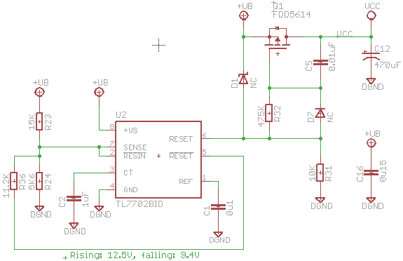
TI TL7702 power supper supervisor is used for monitoring the backup power rail. This is the bipolar high voltage version that works up to 18V (and even available in DIP!). The other variants won't works for this circuit.
This circuit shows how versatile this building block is. It has a timer, a temperature compensated internal reference, open drain true and complement outputs, well defined behaviour down to 1V. To do the same with a dual comparator or a 555 would require a reference source, and more discretes etc, but won't come close.
On the falling edge, /RESET (open collector) is inactive, so R23, R24 forms the voltage divider and determine the falling threshold. V(fall) = 2.53V * (R23 + R24)/R24 = 9.3V
On the rising edge, /RESET is at logic low. So the lower branch of the divider becomes R24 // R36 = 3.73K
V(Rise) = 2.53V * (3.73 + 15) / 3.73 = 12.69V
With the Schottky Or'ing diode drop of about 0.5V under load, we are looking at about 9.8V when the battery will be disconnected. The diode has almost no load prior to reconnecting, so the circuit recovers at just below 13V.
The P-MOSFET is driven from the RESET pin. When RESET is asserted (i.e. undervoltage), the MOSFET gate is raise close to +UB rail, thus turning its output off. When RESET is deasserted, R31 + R32 pulls the gate low. R32 and C5 at the gate of the P-MOSFET converts it into an integrating amplifier whose output rises linearly in response to a step change in its input, limiting the in-rush current to downstream capacitor C12.
Backup Battery Charger: Lead Acid Battery, NiMH/NiCd
Breakout Module
This is the boring part of the design. I used a VME 3 rows DIN receptacle that I removed from old parts for the plug-in power modules. I removed a portion of the connector as it was too wide for my box.
B Row is the ground. The A Row is the output from the power modules. The pins are connected to JP1-3 which is wired to the power cables for my electronics. The C Row is the power input for the modules. A section of it runs directly from the AC Adaptor for the non-essential outputs. The rest are run from the backup power.
Licenses:
Schematic: Creative Commons 4.0 Attribution-ShareAlike 4.0 International
PCB & Layout: Creative Commons 4.0 Attribution-NonCommercial
3D modelling: Creative Commons 4.0 Attribution-ShareAlike 4.0 International
Creative Commons 4.0 Attribution-NonCommercial:
See http://creativecommons.org/licenses/by-nc/4.0/
Creative Commons 4.0 Attribution-ShareAlike 4.0 International
See http://creativecommons.org/licenses/by-sa/4.0/
Files on my github
No comments:
Post a Comment
Note: Only a member of this blog may post a comment.